Self-locking relay and application method thereof

A technology of self-locking relays and locking sleeves, which is applied in the direction of relays, electromagnetic relays, detailed information of electromagnetic relays, etc., can solve the problems of high power consumption and short service life of coils, and achieve the effect of long life

Active Publication Date: 2017-12-01
葛飞凡
View PDF8 Cites 2 Cited by
  • Summary
  • Abstract
  • Description
  • Claims
  • Application Information

AI Technical Summary

Problems solved by technology

The disadvantage of the existing relay is that the coil must be energized all the time to make the relay work, resulting in the disadvantages of high power consumption and short service life of the coil due to long-term energization of the coil

Method used


Image

  • Self-locking relay and application method thereof
  • Self-locking relay and application method thereof
  • Self-locking relay and application method thereof

Examples


Embodiment Construction

[0029] In order to make the objects and advantages of the present invention clearer, the present invention will be further described in detail below in conjunction with the examples. It should be understood that the specific embodiments described here are only used to explain the present invention, not to limit the present invention.

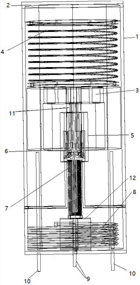
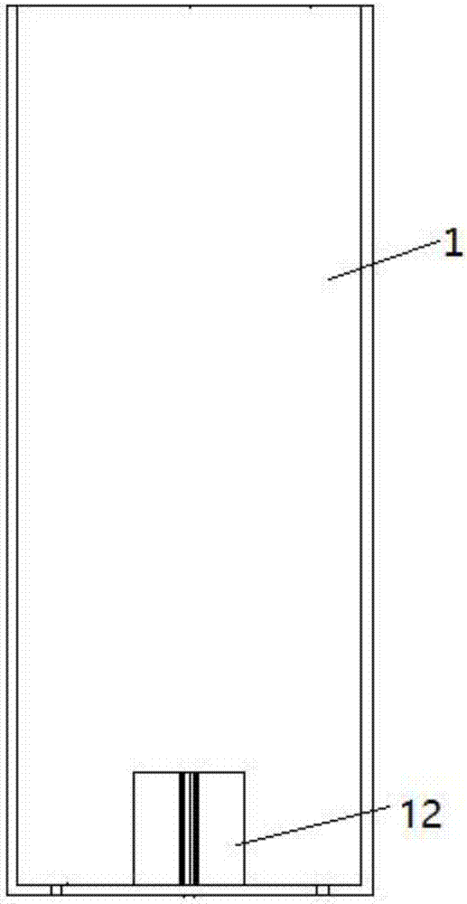
[0030] like Figure 1-Figure 2 As shown, the embodiment of the present invention provides a self-locking relay, which includes a housing 1 and a cover 2 movably installed on the upper end of the housing 1. An armature 3, a push rod lock sleeve 5, and a top rod are installed in the housing 1. Rod 6 and coil 8, the coil 8 is installed horizontally at the inner bottom of the housing 1, the two coil pins 9 of the coil 8 respectively pass through the bottom surface of the housing 1, and the bottom surface of the housing 1 is symmetrically welded with two pins 10, two pins 10 Respectively through the lower bottom surface of the housing 1 and extend t...


PUM


Abstract

The invention discloses a self-locking relay and an application method thereof. The self-locking relay is characterized in that a shell of the self-locking relay is internally provided with an armature, an ejector rod locking sleeve, an ejector rod and a coil, the coil is horizontally installed at the inner bottom end of the shell, two coil pins of the coil respectively penetrate through the bottom surface of the shell, two pins are symmetrically welded on the bottom surface of the shell, the two pins respectively run through the lower bottom surface of the shell and extend to two sides of the ejector rod locking sleeve, an armature abnormal movement prevention spring is installed between one end of the armature and a cover body, the other end is connected with an armature ejector rod, one end, which is provided with tapered teeth, of the armature ejector rod is connected with the armature, the other end is inserted into an opening at one end of the ejector rod locking sleeve, and the other end of the ejector rod locking sleeve is sequentially provided with a shallow groove and a deep groove from the outside in. The self-locking relay does not need to be energized all the time, and the self-locking relay can be controlled to be self-locked or unlocked by only energizing a sucking coil once for a short time, thereby realizing connection or disconnection of a circuit, and always keeping a self-locking or unlocking state until the next time of energization.

Description

technical field [0001] The invention relates to the field of electronic devices, in particular to a self-locking relay and a use method thereof. Background technique [0002] At present, the annual output value of the world's relays reaches 3.9 billion yuan, and the annual sales scale has exceeded 3.3 billion US dollars. In 2000, the output can reach 4.3 billion pieces, and the annual sales scale can reach 3.6 billion US dollars. Among them, the total output of relays in Japan accounts for about 1 / 3 of the world's total output, and the output value of relays in the United States is the highest, accounting for about 1 / 4 of the world's total output value of relays. In recent years, the proportion of the United States and Japan's relay output value in the world's total output value has declined, while Germany's share has risen from 17.47% in 1989 to 25% in recent years. Europe is the largest import and export market for relays. In 1993, the relay market in Western Europe accou...

Claims


Application Information

Patent Timeline
Patent Type & Authority Applications(China)
IPC IPC(8): H01H50/64
CPCH01H50/641H01H50/643
Inventor 葛飞凡
Owner 葛飞凡
Why Eureka
Try Eureka