Contactor

A contactor, contact bridge technology, applied in relays, electromagnetic relays, electromagnetic relay details and other directions, can solve problems such as assembly trouble

Inactive Publication Date: 2017-07-25
陈啸天
View PDF0 Cites 1 Cited by
  • Summary
  • Abstract
  • Description
  • Claims
  • Application Information

AI Technical Summary

Problems solved by technology

In the existing contactor, the static contact is fixed on the base through the static contact, and at the same time, the static contact is also provided with a contact lug, which is used to connect with t

Method used


Image

  • Contactor
  • Contactor

Examples


Embodiment Construction

[0014] The specific implementation manners of the present invention will be further described in detail below in conjunction with the accompanying drawings and embodiments. The following examples are used to illustrate the present invention, but are not intended to limit the scope of the present invention.

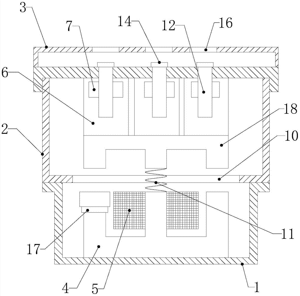
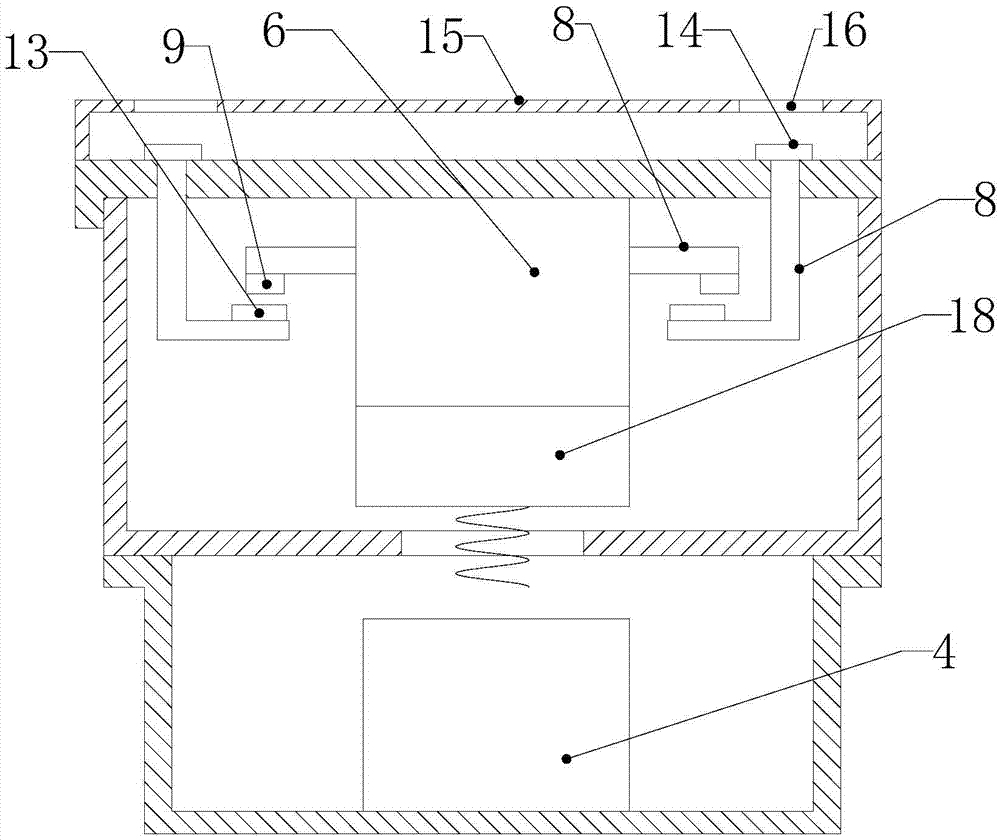
[0015] see Figure 1 to Figure 2 , a contactor according to a preferred embodiment of the present invention includes a base 1, a base 2 and a top cover 3, a static iron core 4 is arranged in the base, an electromagnetic coil 5 is wound on the static iron core, and the base is fixedly arranged on On the top of the base, the base is provided with a contact support 6 and a moving iron core 18, the contact support is fixedly arranged above the moving iron core, and a first through hole 7 is provided on the side of the contact support, and in the first through hole A contact bridge 8 is provided, the two ends of the contact bridge protrude from the through hole and protrude ou...


PUM


Abstract

The invention relates to a contactor, which is easy to assemble and use, and includes a base, a base, and a top cover, a static iron core is arranged in the base, a contact support and a moving iron core are arranged in the base, and the contact support A first through hole is opened on the side surface, and a contact bridge is arranged in the first through hole. The two ends of the bottom surface of the contact bridge are respectively provided with moving contacts, and the bottom surface of the base is opened with a second through hole. The moving iron core and the static An elastic device is arranged between the iron cores, the top cover is fixedly arranged above the base, and a connecting rod is fixedly arranged below the top cover, one end of the connecting rod is fixedly connected with the top cover, and the other end of the connecting rod is provided with a static contact. The static contact is compatible with the moving contact. There is a wiring seat on the upper surface of the top cover, which is electrically connected with the static contact. A protective cover made of insulating material is also provided on the top cover, and the protective cover is hinged. A third through hole is opened on the top cover and the upper surface of the sliding cover, and the third through hole is located directly above the wiring seat.

Description

technical field [0001] The invention relates to a power distribution device, in particular to a contactor. Background technique [0002] A contactor refers to an electrical appliance that uses a coil to flow a current to generate a magnetic field in an industrial electrical system to close the contacts to control the load. The existing contactor includes a base, a base fixedly arranged above the base, a top cover arranged above the base, a static iron core is arranged in the base, and a moving iron core is arranged in the base. When the electromagnetic coil on the static iron core is energized, it attracts the moving iron core, so that the moving contact connected with the moving iron core closes with the static contact fixedly arranged on the base, so that the circuit is conducted. In the existing contactor, the static contact is fixed on the base through the static contact, and at the same time, the static contact is also provided with a contact lug, which is used to conn...

Claims


Application Information

Patent Timeline
IPC IPC(8): H01H50/58H01H50/64H01H50/30
CPCH01H50/58H01H50/30H01H50/645
Inventor 陈啸天
Owner 陈啸天
Why Eureka
Try Eureka