
switch lock

A technology of switch locks and switch pins, which is applied in the direction of building locks, buildings, building fastening devices, etc., can solve the problem of high risk of break-in and theft, and achieve the effect of stabilizing the structure and simplifying assembly

Active Publication Date: 2019-07-16
GEZE GMBH
View PDF6 Cites 0 Cited by
  • Summary
  • Abstract
  • Description
  • Claims
  • Application Information

AI Technical Summary

Problems solved by technology

Therefore, in the switch locks of the type mentioned at the beginning of the text, the risk of breaking the door is relatively high.

Method used


Image

  • switch lock
  • switch lock
  • switch lock

Examples


Embodiment Construction

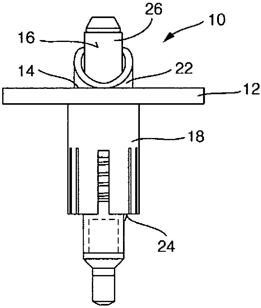
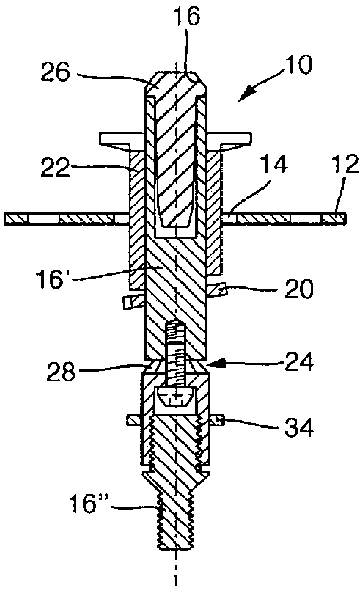
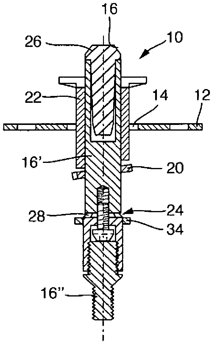
[0030] Figure 1 to Figure 7 Various exemplary embodiments of a switch lock 10 according to the invention, which are provided in particular for long bolt locks on door leaves or the like, are shown. Here, the different switching locks 10 each comprise a lock bar 12 , a lock housing 18 connected to the lock bar 12 , a spring-loaded clamping plate 20 mounted in the lock housing and displaceable in the lock housing 18 . A spring-loaded switch pin 22 passing through the lock bezel 12, said lock bezel having a through hole 14 for the drive pin 16, which is spring-loaded in the direction of the locked position where it moves out, The clamping plate surrounds the drive pin 16 with a clamping ring and the drive pin 16 can be locked in any retracted position via the clamping plate, the switch pin can be pressed into the lock housing 18 against the spring force, To pivot the clamping plate 20 into the release position in which the drive pin 16 is released.

[0031] The lock housing 18...


PUM


Abstract

The invention relates to a switch lock which is provided in particular for an espagnolette lock on a door leaf or the like, comprising a strike plate with a passage opening for a drive bolt which is spring-loaded in the direction of the extended locked position of the drive bolt; a lock housing which is connected to the strike plate; a clamping plate which is accommodated in the lock housing in a spring-loaded manner, a clamping lug of which surrounds the drive bolt, and via which the drive bolt can be blocked in any retracted position; and a spring-loaded latch that can be moved in the lock housing, passes through the strike plate, and can be pushed into the lock housing against the spring force in order to pivot the clamping plate into a release position in which the drive bolt is released. The switch lock additionally comprises a safeguard against push-back, wherein the safeguard can be activated by a pressure being exerted onto a drive bolt portion in the unlocking direction, said drive bolt portion protruding out of the latch when the drive bolt is in the extended locking position, in order to prevent a further movement of the drive bolt in the unlocking direction.

Description

technical field [0001] The invention relates to a switch lock, especially a switch lock for a long bolt lock on a door leaf or the like, the switch lock has a lock baffle, a lock housing connected to the lock baffle, a A spring-loaded clamping plate in the lock housing and a spring-loaded switch pin movable in the lock housing, passing through the lock bezel having a pass for driving the latch hole, the drive pin is spring-loaded in the direction of its extended locking position, the clamping plate surrounds the drive pin with a clamping ring and the drive pin can be locked in any position via the clamping plate In the moved-in position, the switch pin can be pressed into the lock housing against a spring force, so that the clamping plate is pivoted into a release position in which the drive pin is released. Background technique [0002] Additionally, actuated deadbolt switch locks of the type mentioned at the outset are known from EP0348971B1 and CH697988B1. Said drive la...

Claims


Application Information

Patent Timeline
Patent Type & Authority Patents(China)
IPC IPC(8): E05B17/20E05B63/20E05C9/18
CPCE05B17/2084E05B63/20E05C9/18E05B65/1013E05C9/185
Inventor J·勒克尔S·舒恩
Owner GEZE GMBH
Learn More