Mobile rail vehicle collision force measuring wall

A rail vehicle, mobile technology, applied in the field of rail vehicle crash test, to achieve the effect of increasing the collision scene

Active Publication Date: 2017-12-08
SOUTHWEST JIAOTONG UNIV
View PDF13 Cites 14 Cited by
  • Summary
  • Abstract
  • Description
  • Claims
  • Application Information

AI Technical Summary

Problems solved by technology

[0004] The purpose of the present invention is to provide a mobile rail vehicle collision force measuring wall, which can effectively solve the problem of collision force testing in the collision scene of the active and passive test bench collision, and can test the structural end of the rail vehicle driver's cab. The distribution of collision force

Method used


Image

  • Mobile rail vehicle collision force measuring wall
  • Mobile rail vehicle collision force measuring wall
  • Mobile rail vehicle collision force measuring wall

Examples


Embodiment 1

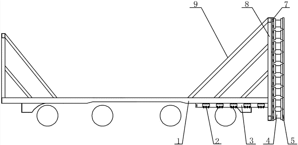
[0032] Collision between the active test rig with components to be tested (cab, energy absorbing device, etc.) and the passive test rig without components to be tested

[0033] In this kind of collision scenario, the front end of the passive test bench is not equipped with test components, the support beam 6 is retracted inside the support beam chute 3, and the support beam chute 3 positioning through hole 3C at both ends and the support beam positioning hole 6B are added. Bolts secure the position of the support beam 6 . Determine the number of force-measuring wall backboards 7 according to the area size of the test collision force, and adjust the position of the collision force test area by adjusting the bolt connection position on both sides of the end wall 8; the force-measuring wall backplane 7 is installed on the passive test bench After the vehicle end wall 8, install the impact force sensor 4 on the transverse T-shaped groove 7B of the force measuring wall back plate 7...

Embodiment 2

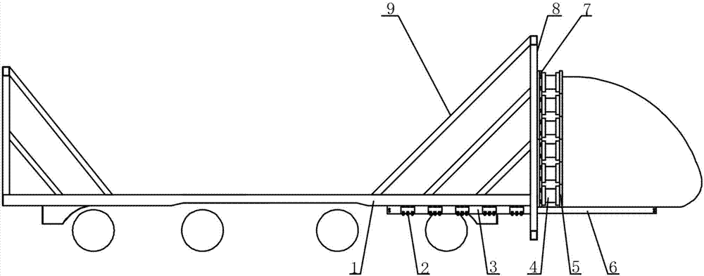
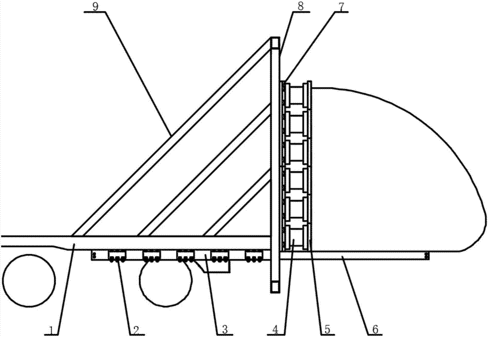
[0035] The active test rig with the driver's cab collided with the passive test rig with the driver's cab

[0036]At the front end of the passive test bench, firstly extend the support beam 6 under the underframe from the support beam chute 3 for an appropriate distance according to the structure of the driver’s cab that needs to be supported, and limit the lateral direction of the support beam 6 by adjusting the lateral position of the rolling bearing 2 Position, so that the lateral distance of the support beam 6 is consistent with the lateral distance of the longitudinal beam of the driver's cab chassis; install an appropriate number of force-measuring wall back panels 7 on the end wall 8 above the support beam 6, adjust the position, and install the impact sensor 4 With the collision panel 5, the collision panel 5 is connected to the driver's cab structure to be collided by bolts, and the lower part of the driver's cab structure is supported by the support beam 6 and connect...


PUM


Abstract

The invention discloses a mobile rail vehicle collision force measuring wall and belongs to the rail vehicle collision test collision force measuring field. The mobile rail vehicle collision force measuring wall mainly comprises an end wall, a support beam chute, a support beam, a force measuring wall backboard, an impact force sensor, a collision panel and the like. The force measuring wall can be used for collision force testing between an active test bench vehicle and a passive test bench vehicle in a collision scene. The testing includes collision between the active test bench vehicle installed with components to be tested, such as a driver cab, an energy-absorbing apparatus and the like, and the passive test bench vehicle which is not installed with the components to be tested, collision of the active and passive test bench vehicles which are installed with a driver cab structure simultaneously, and collision force testing of an contact interface and collision force testing of a rear end of the driver cab structure. A testing area of the collision force of the force measuring wall is adjustable, simultaneously a plurality of driver cab structures can be supported, and the collision scene where collision force testing can be performed in a rail vehicle collision test is increased.

Description

technical field [0001] The invention belongs to the technical field of rail vehicle collision tests, and in particular relates to testing equipment for the value of collision force and the distribution of collision force during the collision test of rail vehicles and parts thereof. Background technique [0002] Crash test is the most direct and convincing method to evaluate the safety of rail vehicles. It is a necessary test for the development of new products for high-speed vehicles, and it is also an important means to judge whether the safety collision energy-absorbing products of rail vehicles can meet the relevant specified indicators. With the rapid development of rail transit, more and more attention has been paid to crash tests. The force measuring wall is used to test the force of the vehicle or its parts in the crash test, and is widely used in the rail vehicle crash test. The force-measuring wall is mainly composed of an impact force sensor and a force-measuring ...

Claims


Application Information

Patent Timeline
Patent Type & Authority Applications(China)
IPC IPC(8): G01M17/08G01M7/08
CPCG01M7/08G01M17/08
Inventor 冯悦肖守讷朱涛阳光武杨冰
Owner SOUTHWEST JIAOTONG UNIV
Why Eureka
Try Eureka