Mechanical limit device and mechanical limit method
A technology of mechanical limit devices and mounting seats, which is applied in mechanical control devices, devices for preventing/limiting/restoring the movement of parts of control mechanisms, instruments, etc., and can solve the problems that limit devices are difficult to achieve fuzzy input and quantitative output.
- Summary
- Abstract
- Description
- Claims
- Application Information
AI Technical Summary
Problems solved by technology
Method used
Image
Examples
Embodiment 1
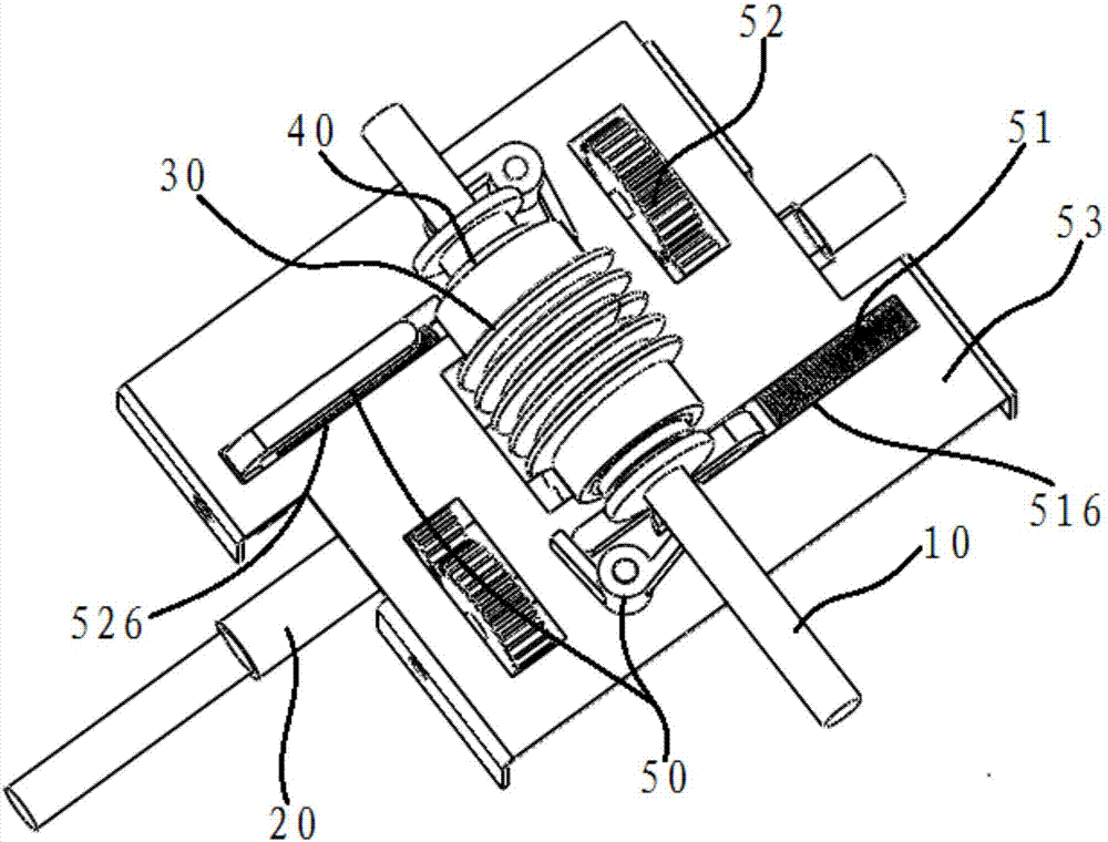
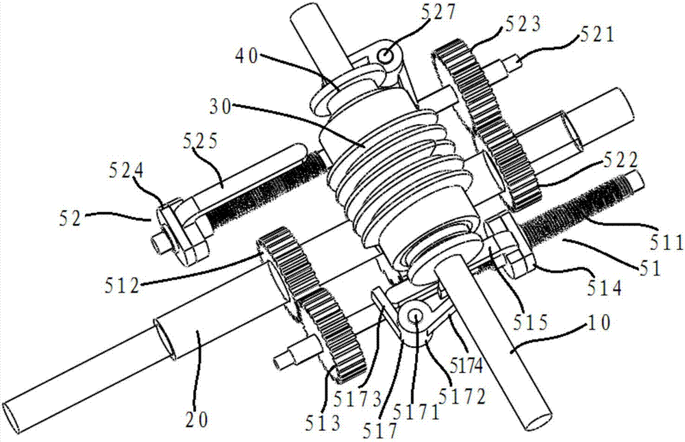
[0053] Such as figure 1 and figure 2 As shown, this embodiment proposes a mechanical limit device, including an input shaft 10, an output shaft 20, a transmission mechanism 30, a slip mechanism 40 with controllable slip direction, and a trigger mechanism for triggering the slip mechanism to slip in different directions 50, the input shaft 10, the transmission mechanism 30 and the output shaft 20 are combined to form a worm gear structure, and the input shaft 10 is connected to the output shaft 20 through the transmission mechanism 30.
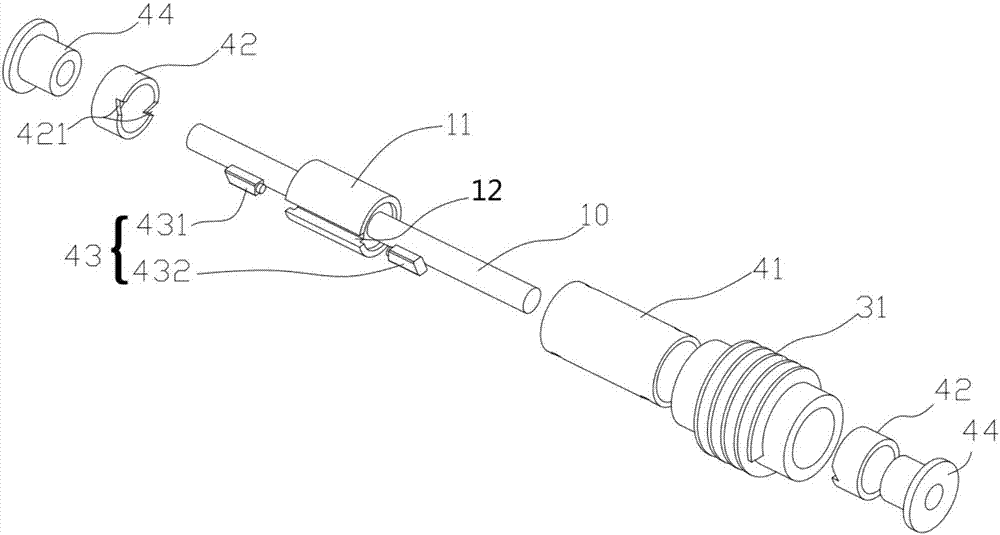
[0054] combine image 3 As shown, the slip mechanism 40 of this embodiment is arranged between the input shaft 10 and the transmission mechanism 30, and the trigger mechanism 50 is associated with the output shaft 20. After the output shaft 20 outputs a predetermined amount, the trigger mechanism 50 triggers the slip mechanism 40, so that Slip occurs between the input shaft 10 and the transmission mechanism 30 .
[0055] Specifically, such ...
Embodiment 2
[0076] This embodiment also proposes another mechanical limiting device, the main difference from the first embodiment lies in the transmission structure and the triggering device.
[0077] like Figure 6 As shown, the input shaft 10, the transmission mechanism 30 and the output shaft 20 of this embodiment are combined to form a cylindrical gear transmission structure, the input shaft 10 and the output shaft 20 are arranged in parallel and side by side, the trigger mechanism 50 includes a screw sleeve 54 and a shift fork 55, the screw sleeve 54 is screwed on the output shaft 20, the shift fork 55 is fixed on the screw sleeve 54, the fork end of the shift fork 55 is clamped on the input shaft 10, and the trigger mechanism 50 follows the rotation of the output shaft 20 and moves axially to the trigger Skid mechanism 40.
[0078] The trigger mechanism of this embodiment is specifically divided into two groups, such as Figure 6 Each set of trigger mechanisms 50 shown includes a...
Embodiment 3
[0083] This embodiment proposes a mechanical limit method. A sliding mechanism with a controllable sliding direction is provided between the input shaft and the transmission mechanism. The additional trigger mechanism triggers the sliding mechanism to slide in different directions, and the The trigger mechanism is associated with the output shaft, so that after the output shaft outputs a predetermined amount, the trigger mechanism triggers the slip mechanism, so that slip occurs between the input shaft and the transmission mechanism, and the output The shaft stops rotating; after the input shaft changes the input rotation direction, the slipping mechanism stops slipping, the transmission mechanism resumes normal transmission work, and drives the output shaft to rotate. After the output shaft outputs a predetermined amount, the trigger mechanism triggers again The slipping mechanism causes slipping between the input shaft and the transmission mechanism, and the output shaft stop...
PUM
 Abstract
Description
Claims
Application Information
 - R&D
- Intellectual Property
- Life Sciences
- Materials
- Tech Scout
- Unparalleled Data Quality
- Higher Quality Content
- 60% Fewer Hallucinations
Browse by: Latest US Patents, China's latest patents, Technical Efficacy Thesaurus, Application Domain, Technology Topic, Popular Technical Reports.
© 2025 PatSnap. All rights reserved.Legal|Privacy policy|Modern Slavery Act Transparency Statement|Sitemap|About US| Contact US: help@patsnap.com


