
Distribution network automation cabinet with function of heat dissipation regulation

An automation cabinet and functional technology, which is applied in substation/power distribution device casing, substation/switch layout details, substation/switchgear cooling/ventilation, etc., can solve the problem of electronic component damage, single function of distribution network cabinet, and heat dissipation Not good and other problems, to achieve the effect of not easy to slip, enhanced practicability, and good heat dissipation effect

Inactive Publication Date: 2017-12-08
宁波智正伟盈信息科技有限公司
View PDF3 Cites 8 Cited by
  • Summary
  • Abstract
  • Description
  • Claims
  • Application Information

AI Technical Summary

Problems solved by technology

[0005] Aiming at the deficiencies of the prior art, the present invention provides a distribution network automation cabinet with the function of adjusting heat dissipation, which solves the problem that the distribution network cabinet has a relatively single function and only serves to protect high-voltage switchgear, and the effect of heat dissipation is not good. Carry out some relatively simple heat dissipation, and the heat dissipation cannot be adjusted, so that the electronic components inside the distribution network automation cabinet will fail or be damaged due to heat, which will reduce the efficiency of the distribution network automation cabinet

Method used


Image

  • Distribution network automation cabinet with function of heat dissipation regulation
  • Distribution network automation cabinet with function of heat dissipation regulation
  • Distribution network automation cabinet with function of heat dissipation regulation

Examples


Embodiment Construction

[0033] The following will clearly and completely describe the technical solutions in the embodiments of the present invention with reference to the accompanying drawings in the embodiments of the present invention. Obviously, the described embodiments are only some, not all, embodiments of the present invention. Based on the embodiments of the present invention, all other embodiments obtained by persons of ordinary skill in the art without making creative efforts belong to the protection scope of the present invention.

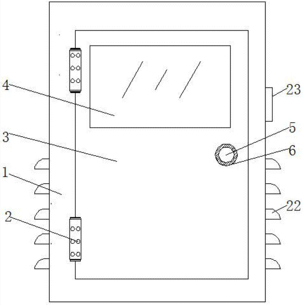
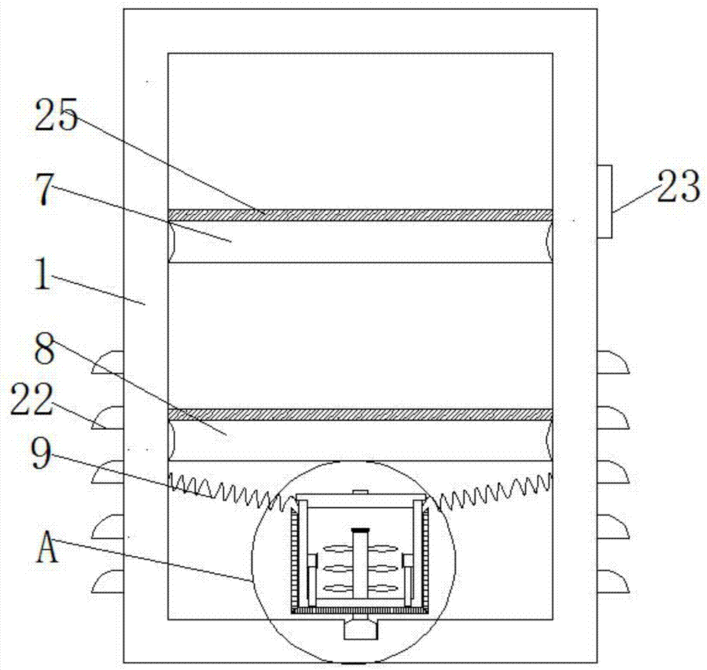
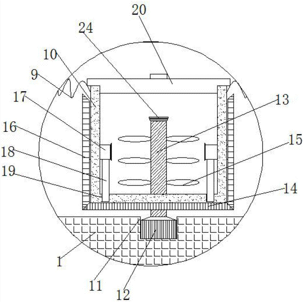
[0034] Such as Figure 1-11As shown, the present invention provides a technical solution: a distribution network automation cabinet with the function of adjusting heat dissipation, including a cabinet body (1), the front of the cabinet body (1) is hinged with a push door (3) through a hinge (2) , the number of hinges (2) is two, and the two hinges (2) are arranged symmetrically with the midline in the horizontal direction of the push door (3), and the front of...


PUM


Abstract

The invention discloses a distribution automation cabinet with a function of heat dissipation regulation. The cabinet comprises a cabinet body, a pushing door is hinged to the front side of the cabinet body through hinges, an observation window is fixed in the front of the pushing door, a handle is fixed below the observation window in the front of the pushing door, a rubber sleeve sleeves the surface of the handle, and a first fixed plate and a second fixed plate are respectively, from top to bottom, fixed on the left and right sides of the inner wall of the cabinet body. In this invention, motors, a rotation shaft, fan blades, a first bevel gear, second bevel gears, rotating rods and supporting plates are provided; the start of the motors is controlled by a switch, if the switch is on, the motors and the rotation shaft rotate, and the fan blades and the first bevel gear rotate simultaneously, and the two engaged second bevel gears rotate, wherein the two second bevel gears are driven to rotate in opposite directions; and then a box cover is lifted up, so the wind generated by the rotation of the fan blades is discharged out of the cabinet body, and the heat of electronic components in the cabinet can be dissipated.

Description

technical field [0001] The invention relates to the technical field of electric power equipment, in particular to a distribution network automation cabinet with the function of regulating heat dissipation. Background technique [0002] The distribution network automation cabinet is a set of high-voltage switchgear installed in a metal or non-metal insulated cabinet or made into an assembled interval ring network power supply unit. Its core part uses a load switch and a fuse, which has a simple structure, small size, With the advantages of low price, improved power supply parameters and performance, and power supply security, it is widely used in distribution stations and box-type substations in load centers such as urban residential quarters, high-rise buildings, large public buildings, and factories and enterprises. [0003] But the current distribution network automation cabinet, the function of the distribution network cabinet is relatively single, only to protect the hig...

Claims


Application Information

Patent Timeline
IPC IPC(8): H02B1/30H02B1/38H02B1/56H02B1/28
CPCH02B1/306H02B1/28H02B1/38H02B1/565
Inventor 朱兰英
Owner 宁波智正伟盈信息科技有限公司
Learn More