Vibration energy harvester induced by driving airflow

An energy harvester and vibration-inducing technology, applied in electrical components, piezoelectric effect/electrostrictive or magnetostrictive motors, generators/motors, etc., can solve the difficulty of subsequent maintenance of cables, limited battery life, Inconvenient use and other problems, to achieve the effect of improving power generation and power supply capacity, simple structure and high reliability

Active Publication Date: 2019-01-11
ZHEJIANG NORMAL UNIVERSITY
View PDF5 Cites 0 Cited by
  • Summary
  • Abstract
  • Description
  • Claims
  • Application Information

AI Technical Summary

Problems solved by technology

If the traditional cable is used for power supply, the cable laying and subsequent maintenance are more difficult and costly; if the battery is used for power supply, due to the limited life of the battery, it needs to be replaced frequently, which is extremely inconvenient to use, especially in remote mountainous areas

Method used


Image

  • Vibration energy harvester induced by driving airflow
  • Vibration energy harvester induced by driving airflow
  • Vibration energy harvester induced by driving airflow

Examples


Embodiment Construction

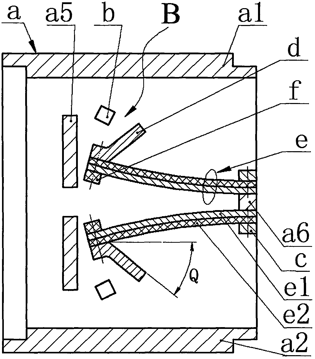
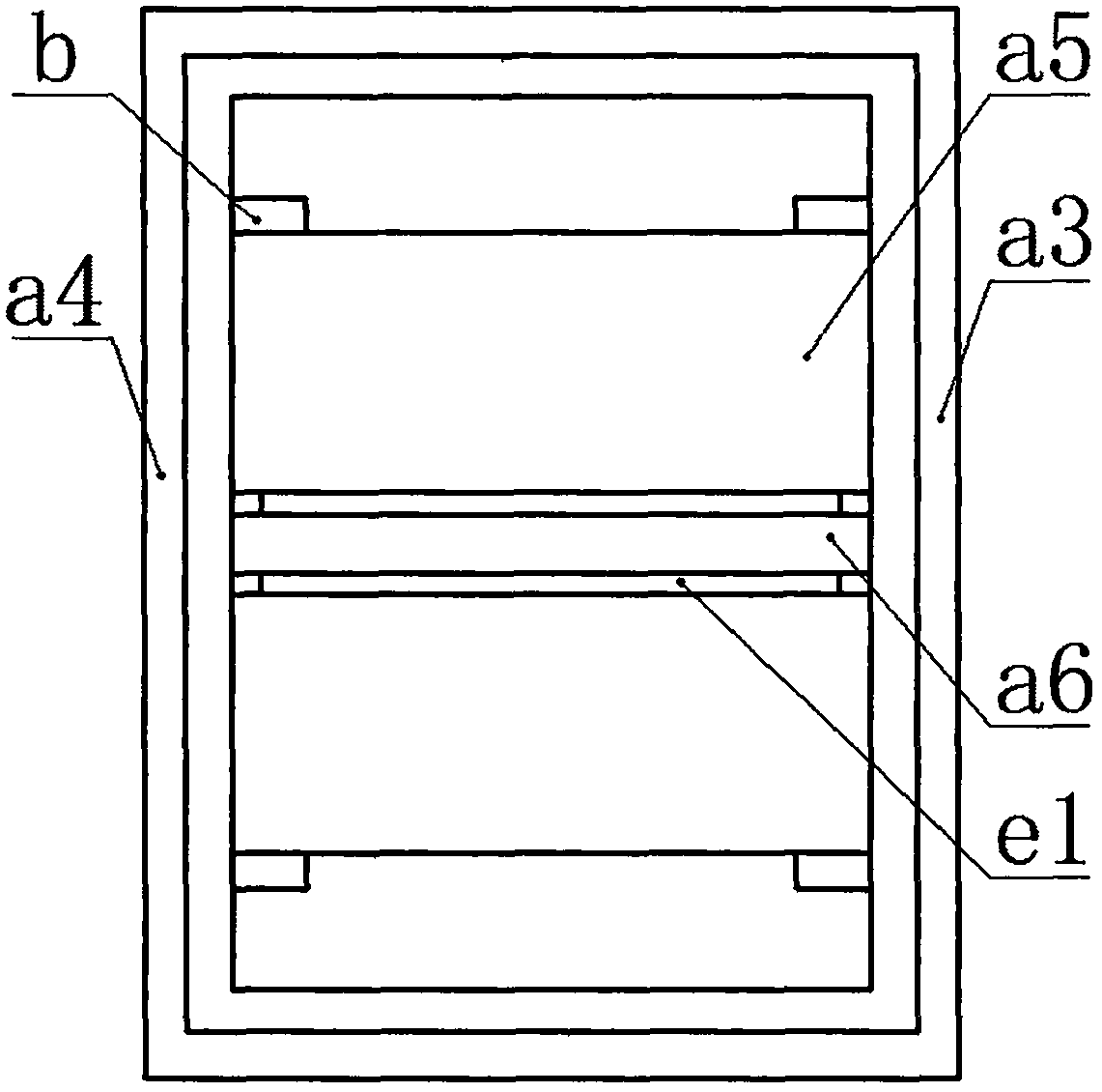
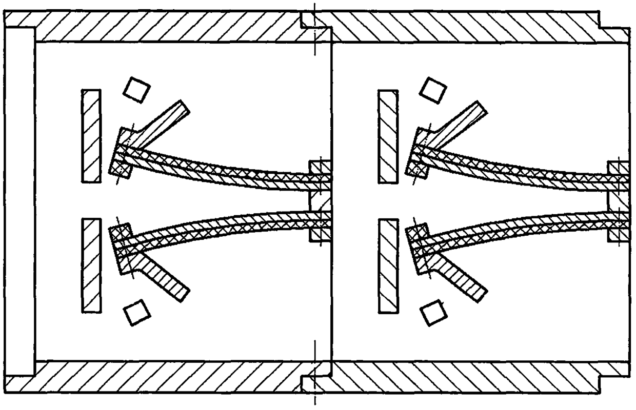
[0014] The shell a is composed of a top wall a1, a bottom wall a2, a front wall a3, and a rear wall a4. The inner left side of the shell a is provided with two wind deflectors a5, and the inner right side of the shell a is provided with a cross beam a6. Both ends of the wind plate a5 and the cross beam a6 are respectively fixed on the front wall a3 and the rear wall a4; the inner side of the front wall a3 and the rear wall a4 near the wind baffle a5 are installed with two limit blocks b by screws. The wind plate a5 and the limit block b are arranged symmetrically on the upper and lower sides of the symmetry center of the beam a6; the upper and lower sides of the beam a6 are installed with piezoelectric vibrators e through the pressure plate c and screws, and the piezoelectric vibrators e are in contact with the beam a6 The surface is a horizontal plane, the two sides of the free end of the piezoelectric vibrator e are respectively installed with a windward plate d and a magnet f...


PUM


Abstract

The invention relates to a driving airflow induced vibration energy harvester, and belongs to the field of new energy. A shell is provided with two wind deflectors at the left side and provided with a crossbeam at the right side. Two limit blocks are mounted on left sides of front and back walls of the shell. Piezoelectric vibrators are mounted on upper and lower sides of the crossbeam. Contact surfaces between the piezoelectric vibrators and the crossbeam are horizontal planes. Two sides of a free end of each piezoelectric vibrator are respectively provided with a windward plate and a magnet. The magnets on the piezoelectric vibrators on the upper and the lower sides of the crossbeam are close to each other and provided with the same-polarity magnetic poles being relatively close to each other. Each piezoelectric vibrator is formed by bonding a thick substrate and a piezoelectric plate, with the substrate being mounted near the crossbeam and the windward plate being mounted near the piezoelectric plate. Each piezoelectric vibrator has a straight structure before mounting and has a bent structure after the mounting. The wind blows to the left side from the right side of the shell so that the windward plates and the magnetic plates swing in a reciprocating manner, when the free ends of the piezoelectric vibrators are abutted on the limit blocks, the deformation amount is less than an allowable value thereof, and the deformation amount is zero when the magnets on the piezoelectric vibrators are abutted against each other. At a rated wind speed, the static deformation amount of the piezoelectric vibrators is half its allowable value.

Description

Technical field [0001] The invention belongs to the technical field of new energy, and specifically relates to a driving airflow-induced vibration energy collector, which supplies power to instruments and equipment in railways and highway tunnels. Background technique [0002] Tunnels have become an important part of the current highway and railway network. In order to ensure that cars and trains can travel normally and safely, and to achieve real-time monitoring of the tunnel environment and passing vehicles, various instruments and lighting facilities need to be installed in the tunnel, so there must be corresponding power supply facilities in the tunnel. If the traditional cable is used for power supply, cable laying and subsequent maintenance are more difficult and costly; if the battery is used for power supply, the battery life is limited and needs to be replaced frequently, which is extremely inconvenient to use, especially in remote mountainous areas. Summary of the inve...

Claims


Application Information

Patent Timeline
Patent Type & Authority Patents(China)
IPC IPC(8): H02N2/18
CPCH02N2/185
Inventor 郑佳佳钱前程王淑云
Owner ZHEJIANG NORMAL UNIVERSITY
Why Eureka
Try Eureka