A self-powered fuel heater

A fan heater, self-powered technology, applied in air heaters, lighting and heating equipment, fluid heaters, etc., can solve the problems of fast cold wind speed, external power supply, inability to adjust the fuel injection volume, etc., to improve power generation and Efficiency, reduced size and weight, self-powered operation

Active Publication Date: 2016-01-13
中国人民解放军32181部队
View PDF8 Cites 0 Cited by
  • Summary
  • Abstract
  • Description
  • Claims
  • Application Information

AI Technical Summary

Problems solved by technology

However, there are many deficiencies in the above two kinds of heating equipment: for example, the heating system with hot water or steam as the heating medium has the defects of excessive initial investment, large floor area, long construction period, cumbersome operation and maintenance, and environmental pollution. Although the heating equipment with electricity as the heat source is convenient to use, it is difficult to achieve large-scale heating
However, the existing heater has the following disadvantages: the one is that the wind speed of the cold wind sucked by the fan blades is relatively fast, which easily causes the flame burning in the combustion tube to be unstable; Sufficient, and the fuel injection volume cannot be adjusted
The above method is helpful to improve the combustion efficiency of the heater, but the effect is not ideal
In addition, the biggest disadvantage of camping oil heaters is that they need an external power supply during operation. When the power supply equipment is maintained or fails, the heater is forced to stop and stop heating.

Method used


Image

  • A self-powered fuel heater
  • A self-powered fuel heater

Examples


Embodiment Construction

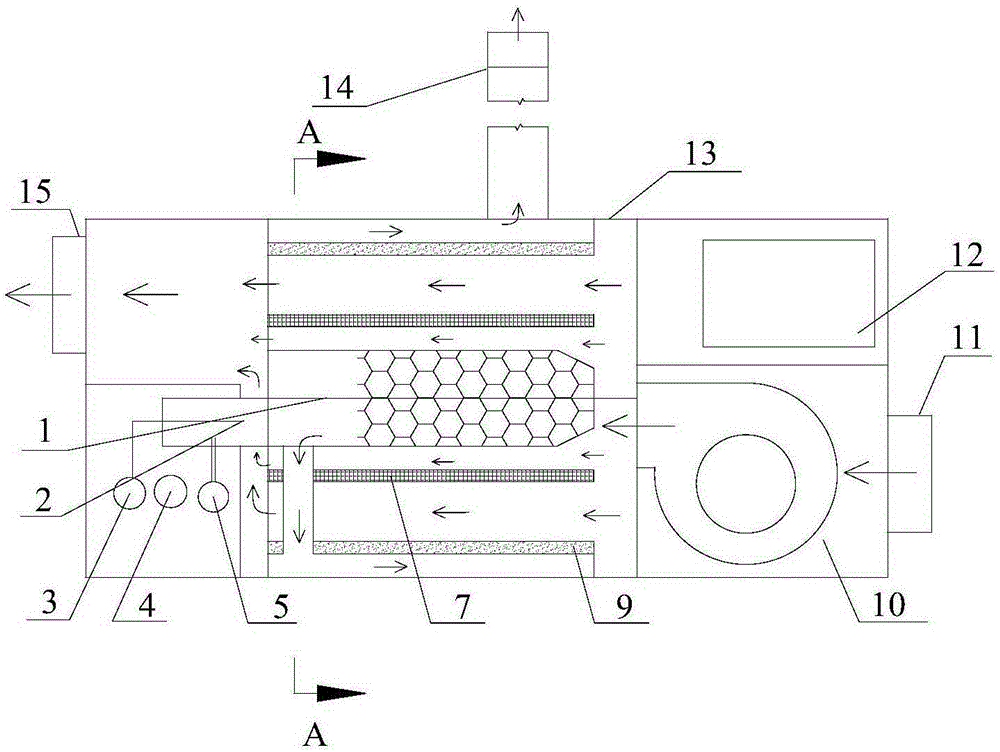
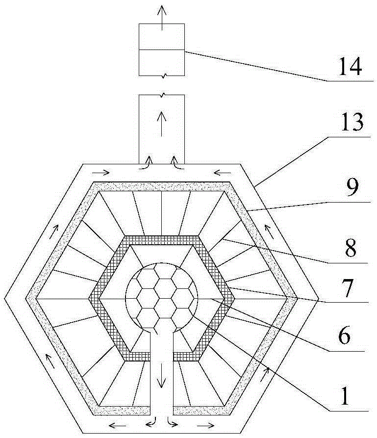
[0021] The present invention will be described in further detail below in conjunction with the accompanying drawings.

[0022] see Figure 1-2 , the present invention comprises shell 13 that has chimney 14, and the control system that is used to control temperature and air blower is arranged on shell 13, and cylindrical combustion chamber 1 with flue gas outlet is arranged in shell 13, and one end of combustion chamber 1 is provided with burner 2. The other end is provided with a blower 10, and the outer side of the combustion chamber 1 is provided with a first heat conduction layer and a second heat conduction layer in sequence. The high temperature thermoelectric module 7 is fixed on the first heat conduction layer, and the low temperature thermoelectric module is fixed on the second heat conduction layer. 9. The first heat conduction layer and the second heat conduction layer are regular prismatic structures with several heat conduction plates opening at both ends of the wa...


PUM


Abstract

A self-powered fuel oil fan heater comprises an outer shell provided with a chimney, wherein the outer shell is provided with a control system used for controlling the temperature and an air feeder, a combustion chamber provided with a smoke outlet is arranged inside the outer shell, a combustor is arranged at one end of the combustion chamber, the air feeder is connected to the other end of the combustion chamber, the outer side of the combustion chamber is sequentially provided with a first heat conduction layer, a second high-temperature thermoelectric module and a low-temperature thermoelectric module from inside to outside in a sleeved mode, the high-temperature thermoelectric module is connected with the combustion chamber through a plurality of rib plates, the high-temperature thermoelectric module is connected with the low-temperature thermoelectric module through a plurality of heat exchangers, and electricity produced by the high-temperature thermoelectric module and the low-temperature thermoelectric module is provided for the combustor and the air feeder; heat exchanging is carried out on air sucked in by the air feeder, the rib plates and the heat exchangers, and then heat is directly provided for a user. The self-powered fuel oil fan heater can provide electricity and heat energy for heating at the same time, has the advantages of being high in energy efficiency and stability, convenient to move and the like, is ideal equipment for heating in camping or temporary housing, and can be widely applied to indoor heating in buildings, agricultural greenhouses, tents, mobile houses and other facilities.

Description

technical field [0001] The invention relates to a combustion device for self-supply and power supply, in particular to a self-supply fuel oil heater. Background technique [0002] In most parts of our country, heating equipment is needed in winter, and the heating equipment commonly used at present is mainly the heating system with hot water or steam as the heat medium, such as boilers, radiators and heaters; the heating equipment with electricity as the heat source, such as electric heater. However, there are many deficiencies in the above two kinds of heating equipment: for example, the heating system with hot water or steam as the heating medium has the defects of excessive initial investment, large floor area, long construction period, cumbersome operation and maintenance, and environmental pollution. Although the heating equipment with electricity as the heat source is convenient to use, it is difficult to realize large-area heating. The heater has good air quality, n...

Claims


Application Information

Patent Timeline
Patent Type & Authority Patents(China)
IPC IPC(8): F24H3/06F24H9/18F24H9/20
Inventor 黄光宏高怀斌李洪峻李俊胡云俊
Owner 中国人民解放军32181部队
Why Eureka
Try Eureka