Power transmission line galloping state on-line monitoring system based on piezoelectric vibration energy collector

An energy harvester, piezoelectric vibration technology, applied in signal transmission systems, piezoelectric effect/electrostrictive or magnetostrictive motors, generators/motors, etc., can solve the problem that sensor nodes cannot obtain long-term stable power supply, etc. problem, to achieve the effect of self-powered operation and high-efficiency conversion

Pending Publication Date: 2022-07-15
CHONGQING UNIV OF POSTS & TELECOMM
View PDF5 Cites 0 Cited by
  • Summary
  • Abstract
  • Description
  • Claims
  • Application Information

AI Technical Summary

Problems solved by technology

[0006] In view of this, the object of the present invention is to provide an online monitoring system for the galloping state of transmission lines based on piezoelectric vibration energy harvesters, to solve the problem that the sensing nodes cannot obtain long-term stable power supply during the online monitoring process of the galloping state of transmission lines

Method used


Image

  • Power transmission line galloping state on-line monitoring system based on piezoelectric vibration energy collector
  • Power transmission line galloping state on-line monitoring system based on piezoelectric vibration energy collector
  • Power transmission line galloping state on-line monitoring system based on piezoelectric vibration energy collector

Examples


Embodiment 1

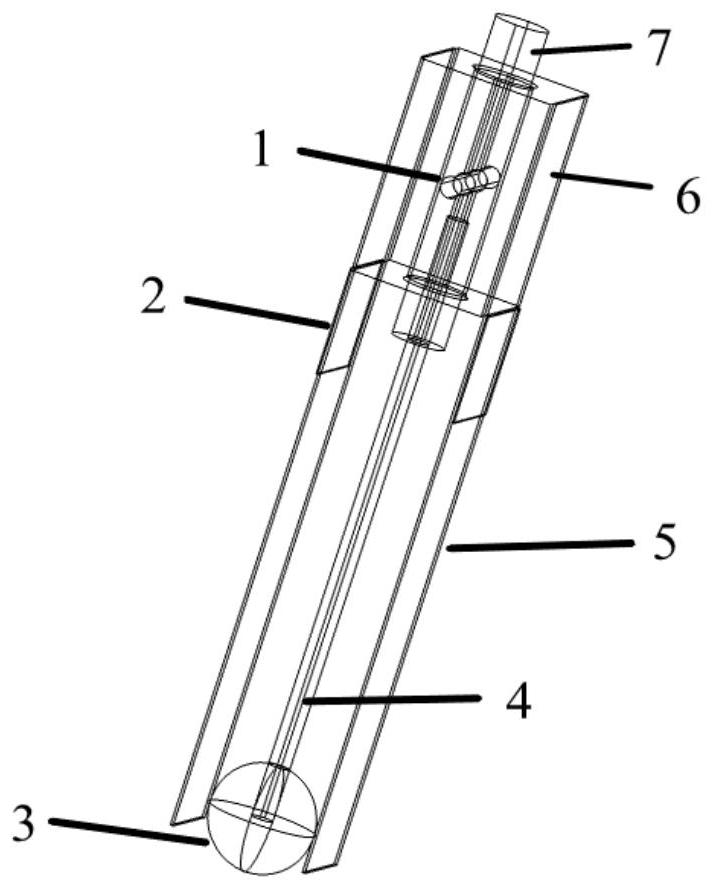
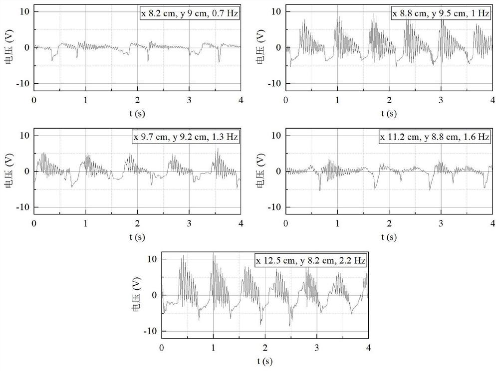
[0032]In the finite element environment, a piezoelectric vibration generator model suitable for typical operation scenarios of transmission lines is constructed. The initial simulation parameters of the given model include: the size of the base is 25*30*40mm; the radius of the pendulum base is 4.95mm, and the height is 40mm. The support joint is a cylinder with a radius of 2mm and a height of 30mm; the pendulum rod is a cylinder with a radius of 2mm and a height of 120mm; the pendulum ball is a ball with a radius of 10mm. Paste two 0.5*25*145mm elastic copper beams in the horizontal x direction of the base, and paste 0.4*25*20mm piezoelectric sheets on the copper beams. By simulating the galloping state of the transmission line (the galloping frequency is 0.1-3Hz), the open-circuit voltage and short-circuit current are obtained, such as image 3 , Figure 4 shown. Under the conditions of compound galloping frequency of 1Hz, horizontal amplitude of 8.8cm, and vertical amplitu...


PUM


Abstract

The invention relates to a piezoelectric vibration energy collector-based power transmission line galloping state on-line monitoring system, and belongs to the technical field of intelligent power grids. The system comprises a piezoelectric vibration energy collector, a distributed sensor, a wireless sensing module and a processor, along with continuous occurrence of line galloping, the piezoelectric vibration energy collector is driven to realize electromechanical energy conversion in a line galloping state, and power is supplied to the distributed sensor and the wireless sensing module. The piezoelectric vibration energy collector comprises a base, a swing base, a supporting joint for connecting the swing base and the base, a swing rod, a swing ball, a metal beam and a piezoelectric plate. The swing base swings around the supporting joint along the plane where the swing base is located at a small angle to drive the swing ball to impact the metal beam, and the metal beam vibrates to enable the piezoelectric plate to be pressed to generate charges. According to the invention, self-powered operation of the power transmission line galloping on-line monitoring device is realized.

Description

technical field [0001] The invention belongs to the technical field of smart grids, and relates to an on-line monitoring system for the galloping state of transmission lines based on piezoelectric vibration energy collectors. Background technique [0002] Power transmission lines exposed to natural conditions for a long time not only face natural damage such as subsidence, landslides, pollution, strong wind and lightning strikes, but also bear the line galloping problems caused by factors such as icing loads and wind loads. The galloping of transmission lines often leads to the damage of various devices and equipment on the line. In severe cases, it is easy to cause interphase flashover of the transmission line, causing line tripping and power failure, or causing wire strand breaks, tower collapse and other accidents, which seriously threaten the stable operation of the power transmission network. cause significant economic losses. Therefore, in order to reduce the occurren...

Claims


Application Information

Patent Timeline
Patent Type & Authority Applications(China)
IPC IPC(8): H02N2/18G01D21/02G08C17/02
CPCH02N2/186G01D21/02G08C17/02
Inventor 高思航冯少轩孙卓立邓小童邓晴文徐菁陈怡多曾锡松兰文宇周杰
Owner CHONGQING UNIV OF POSTS & TELECOMM
Why Eureka
Try Eureka