Light emitting device with excellent heat resistance and light resistance

a light-emitting device and heat-resistance technology, which is applied in the direction of discharge tube luminescnet screens, natural mineral layered products, transportation and packaging, etc., can solve the problems of reducing the mechanical strength affecting the quality of the cured product, so as to achieve excellent heat-resistance and light-resistance. excellent, small birefringence

Active Publication Date: 2006-10-12
NICHIA CORP
View PDF6 Cites 61 Cited by
  • Summary
  • Abstract
  • Description
  • Claims
  • Application Information

AI Technical Summary

Benefits of technology

[0016] A resin layer used in a light emitting device of the present invention is constructed as a phosphor-containing layer or a lens or the like, and because the resin layer exhibits excellent transparency, with almost no light absorption in the region from 300 nm to 800 nm, as well as a small birefringence, it is ideally suited to these applications. In addition, the resin layer also exhibits excellent heat resistance and light resistance, as well as superior toughness, meaning it is resistant to deterioration even when molded directly on top of a light emitting element such as a LED. Moreover, in a light emitting device of the present invention, because the light emitting element is mounted by eutectic bonding to a package at least partially comprised of metal, the heat radiation properties of the device are also favorable. As a result of these characteristics operating in unison, the heat from the light emitting element is not retained, but is rather released externally, meaning the resin undergoes no deterioration, enabling stable and favorable light emission characteristics to be maintained over an extended period.
[0017] Furthermore, by using eutectic bonding, the bonding strength is increased and the adhesion between the silicone resin layer and the metal member improves, enabling an improvement in the reliability of the product.
[0018] If the resin layer comprises a phosphor, then when the light emitted from the light emitting element is irradiated onto the phosphor, the phosphor absorbs the light and performs a wavelength conversion. As a result, the light emitted from the light em...

Problems solved by technology

Because silethylene linkages are prone to cleavage by light or heat, the main skeleton within the cured product is prone to deterioration, and the resin is prone to bleed-out of low molecular weight, fluid, oily silicone.
As a result, the mechanical strength of the cured product falls, and the resin is more likely to become brittle and prone to heat deformation.
Furthermore, the low molecular weigh...

Method used


Image

  • Light emitting device with excellent heat resistance and light resistance
  • Light emitting device with excellent heat resistance and light resistance
  • Light emitting device with excellent heat resistance and light resistance

Examples


embodiment

[0094] As follows is a description of specifics regarding the structure of a light emitting device of the present invention, based on the embodiment shown in the drawings.

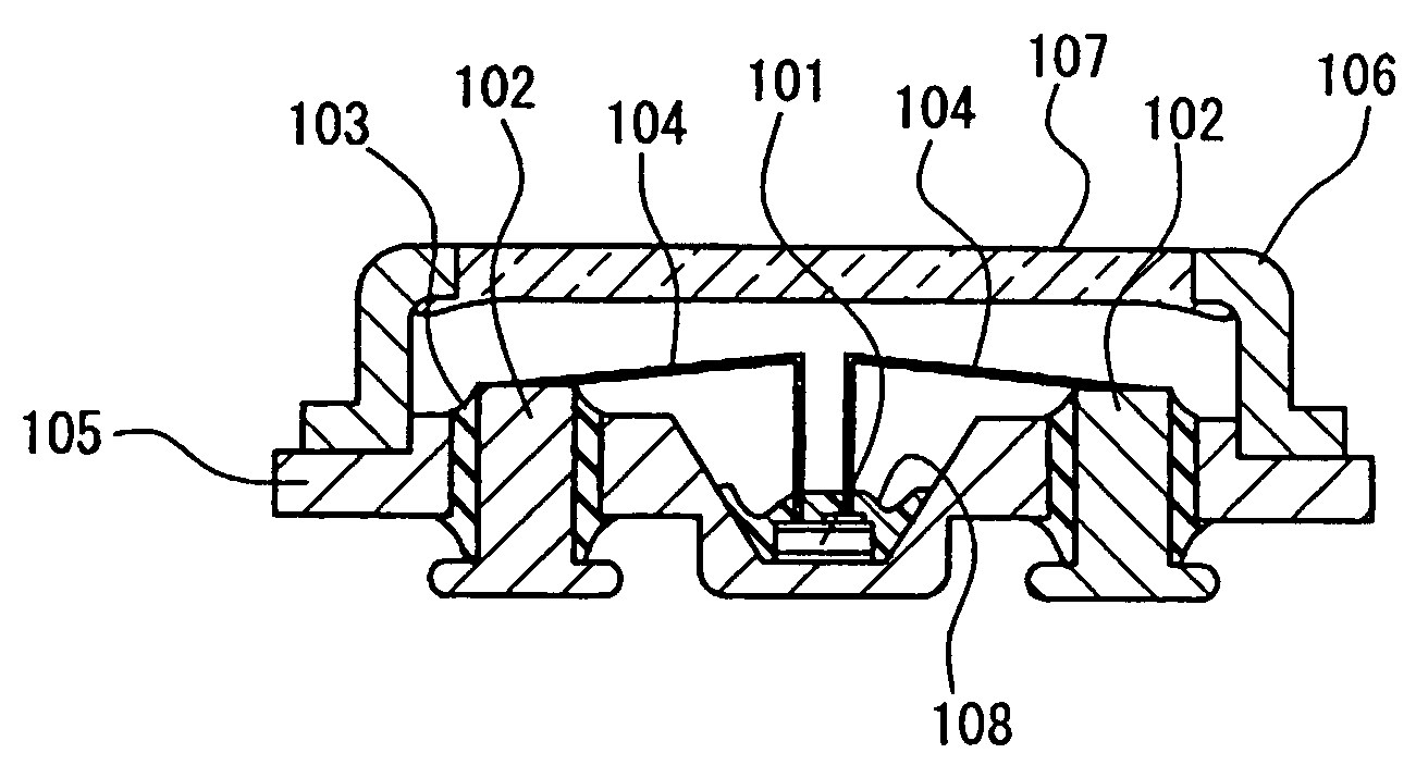
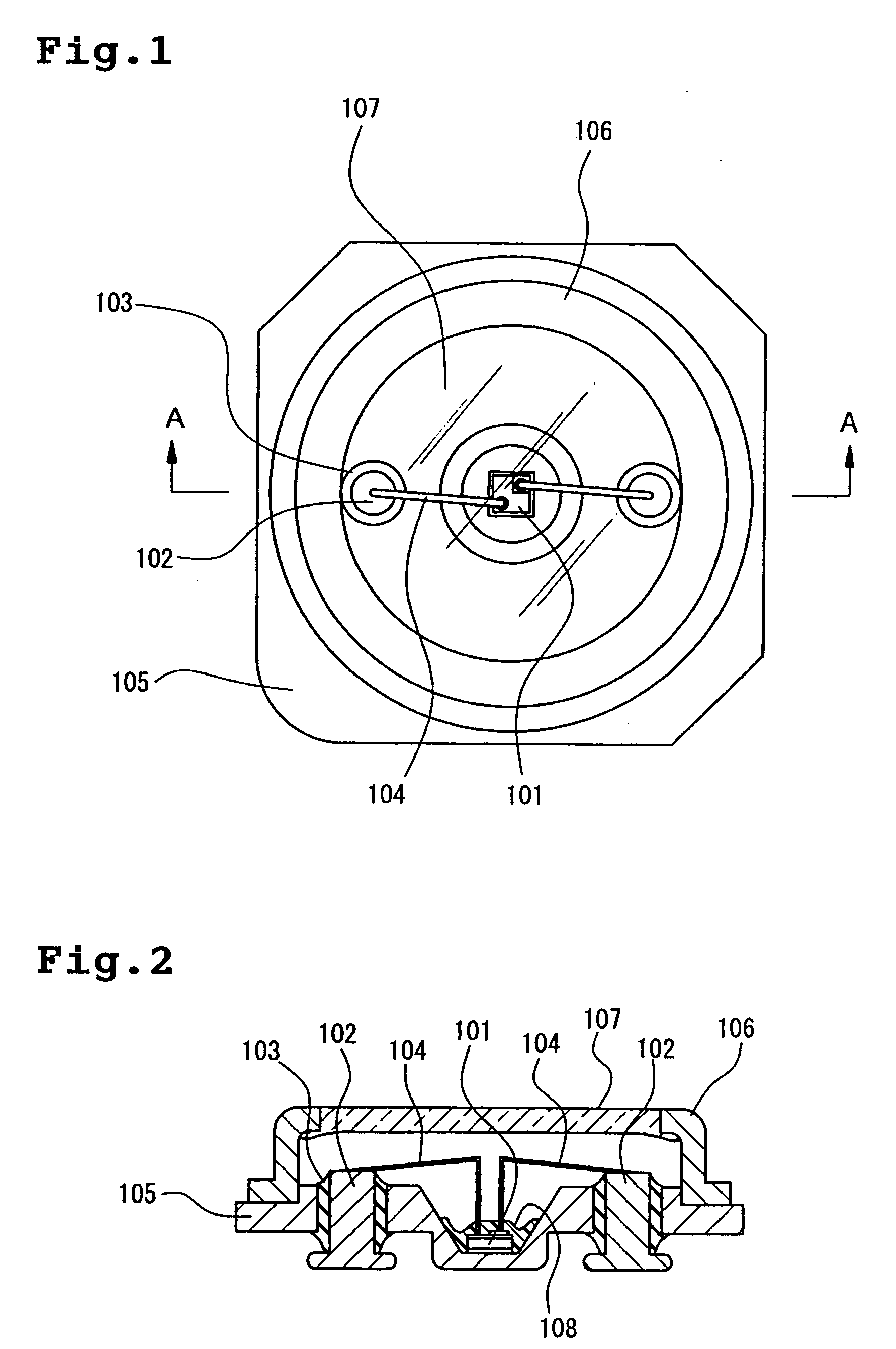
[0095]FIG. 1 is a plan view showing an outline of a light emitting device, FIG. 2 is a longitudinal sectional view of the same device along a cross section substantially along the line A-A, that is, along the two wires 104.

[0096] A light emitting device according to this embodiment forms a surface mounted light emitting device, but this is merely an example, and other types of light emitting device such as a bullet-type device are also possible. A light emitting element 101 can use an ultraviolet light excited nitride semiconductor light emitting element. Furthermore, the light emitting element 101 can also use a blue light excited nitride semiconductor light emitting element. This description assumes an ultraviolet light excited light emitting element 101. The light emitting element 101 uses a nitride semiconduc...

synthesis examples

[0102] The methyltrimethoxysilane used in Synthesis Examples is KBM13 (a brand name) manufactured by Shin-Etsu Chemical Co., Ltd., and the dimethyldimethoxysilane is KBM22 (a brand name), also manufactured by Shin-Etsu Chemical Co., Ltd.

synthesis example 1

[0103] A stirrer and a condenser tube were fitted to a 1 L three-neck flask. This flask was then charged with 109 g (0.8 mols) of methyltrimethoxysilane, 24 g (0.2 mols) of dimethyldimethoxysilane, and 106 g of isobutyl alcohol, and the mixture was cooled in ice with constant stirring. With the temperature inside the reaction system maintained at 0 to 20° C., 60.5 g of 0.05 N hydrochloric acid solution was added dropwise. Following completion of the dropwise addition, the reaction mixture was stirred for 7 hours under reflux at 80° C. Subsequently, the reaction solution was cooled to room temperature, and 150 g of xylene was added to dilute the reaction solution. The reaction solution was then poured into a separating funnel, and washed repeatedly with 300 g samples of water until the electrical conductivity of the separated wash water fell to no more than 2.0 μS / cm. The water was then removed from the washed reaction solution by azeotropic distillation, and following adjustment of ...


PUM

PropertyMeasurementUnit
Percent by massaaaaaaaaaa
Wavelengthaaaaaaaaaa

Abstract

A light emitting device is provided, including a light emitting element, a package comprised at least partially of metal on which said light emitting element is mounted, and a resin layer coated on said light emitting element. The light emitting element is eutectic bonded to a metal portion of said package, and the resin layer is formed of a cured product of a silicone composition. The composition includes (i) an organopolysiloxane having an average composition formula (1):
R1a(OX)bSiO(4−a−b)/2   (1)
wherein R1 is an alkyl, alkenyl or aryl group, X is a hydrogen atom, or an alkyl, alkenyl, alkoxyalkyl or acyl group, a is a number from 1.05 to 1.5, b is a number of 0<b<2, and 1.05<a+b<2, and (ii) a condensation catalyst. The device exhibits improved heat resistance and light resistance, and also exhibits improved adhesion to the resins and metal members used.

Description

BACKGROUND OF THE INVENTION [0001] 1. Field of the Invention [0002] The present invention relates to a light emitting device that can be used in a liquid crystal backlight, an illumination light source, and various types of indicators, displays and traffic signal lights, and relates particularly to a light emitting device with improved levels of heat resistance and light resistance. [0003] 2. Description of the Prior Art [0004] In light emitting devices that use a light emitting element such as an LED, the light emitting element is typically coated with a layer comprising a phosphor for converting the wavelength of the light, or an organic resin layer with a high degree of optical transparency that functions as a lens or the like. When current flows through the light emitting element, the element heats up to a temperature of 100° C. to 130° C. Furthermore, light emitting elements that emit blue light or ultraviolet light from the short wavelength region are now being used, meaning r...

Claims


Application Information

Patent Timeline
IPC IPC(8): H01L51/52H05B33/04H01L33/30H01L33/06H01L33/40H01L33/50H01L33/54H01L33/56H01L33/62
CPCC08G77/18Y10T428/23H01L33/56H01L51/5237H01L2224/48465H01L2224/49107H01L2224/73265Y10S428/917H01L24/45C09D183/04H01L2224/8592H01L2924/3025H01L2224/45144H01L2924/00014H01L2924/00H01L2924/01322H01L2924/12036H01L2924/12041Y10T428/31663H10K50/8423H10K50/8426
Inventor SOFUE, SHINSUKETAMAKI, HIROTOIZUNO, KUNIHIRO
Owner NICHIA CORP
Why Eureka
Try Eureka