A Method for Calculating the Thermal Efficiency of Pipelines in Large Thermal Power Plants

A thermal power plant, thermal efficiency technology, applied in computing, data processing applications, energy industry, etc., can solve problems such as overestimation, inaccurate pipeline efficiency, and underestimation of pipeline impact

Active Publication Date: 2020-05-12
青岛鸿瑞电力工程咨询有限公司
View PDF20 Cites 0 Cited by
  • Summary
  • Abstract
  • Description
  • Claims
  • Application Information

AI Technical Summary

Problems solved by technology

However, the calculation of pipeline efficiency through enthalpy change is inaccurate and may be overestimated, resulting in a disadvantageous position for EPC contractors when making performance guarantees, increasing the risk of being assessed and the cost of fines, both domestically and internationally. The thermal economy of the power plant is closely related to the thermal efficiency of the pipeline
However, people tend to unilaterally think that the thermal efficiency of pipelines only reflects the insulation and leakage of pipelines, and ignores the loss of working capacity caused by the heat loss of working fluid flow, thus underestimating the impact of pipeline heat loss

Method used


Image

  • A Method for Calculating the Thermal Efficiency of Pipelines in Large Thermal Power Plants
  • A Method for Calculating the Thermal Efficiency of Pipelines in Large Thermal Power Plants

Examples


Embodiment Construction

[0025] The present invention will be described in detail below in conjunction with the accompanying drawings and embodiments.

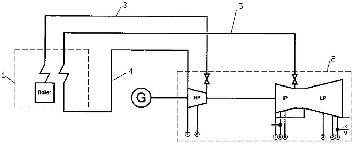
[0026] The present invention is mainly applicable to steam pipeline systems of large-scale (power generation greater than 125MW) thermal power plants, such as figure 1 , and its piping system includes main steam pipes, 3, cold reheating pipes 4 and hot reheating pipes 5. The boiler system 1 communicates with the steam turbine system 2 through the main steam pipeline 3, and the steam turbine system 2 flows back to the boiler system 1 through the cold reheat pipeline 4, and then enters the steam turbine system from the filter system 1 through the hot reheat pipeline 5.

[0027] Next, calculate the overall pipeline thermal efficiency of the main steam pipeline 3 , the cold reheat pipeline 4 and the hot reheat pipeline 5 using the method described in this application.

[0028] The specific calculation process of this embodiment is as follows.

[0029] T...


PUM


Abstract

The invention discloses a method of calculating pipeline heat efficiency of a large thermal power plant. Pipelines of the power plant comprise a main steam pipeline, a cold reheating pipeline and a heat reheating pipeline, and are characterized in that heat losses in each pipeline include a flow loss Q<1> and a heat dissipation loss Q<2>, the flow loss Q<1> = (S - S<a1>) x T<a1> x D<0>, the heat dissipation loss Q<2> = (S<a2> - S<a1>) x T<a2> x D<0>, the flow loss Q<11> and the heat dissipation loss Q<21> of the main steam pipeline, the flow loss Q<12> and heat dissipation loss Q<22> of the cold reheating pipeline and the flow loss Q<13> and heat dissipation loss Q<23> of heat reheating pipeline are respectively calculated, the pipeline heat efficiency eta = 1 - (Q<11> + Q<12> + Q<13> + Q<21> + Q<22> + Q<23>) / Q, the Q therein is a heat load of a boiler outlet, and assessing heat economy of a steam-turbine generator set and correctly analyzing heat economy of the whole power plant are facilitated.

Description

technical field [0001] The invention belongs to the field of thermal efficiency calculation of a thermal system of a large-scale thermal power plant, and specifically relates to a method for calculating the thermal efficiency of a pipeline of a large-scale thermal power plant. Background technique [0002] During the implementation of domestic or international large-scale thermal power plant projects, thermal economics will be evaluated. In the total thermal efficiency of large-scale thermal power plants, the thermal efficiency of pipes is one of its important components and has great potential. In the current conventional calculation method, the pipeline efficiency takes into account heat loss, auxiliary system loss and leakage loss of working fluid with heat. When calculating the heat dissipation loss of the pipeline, the heat dissipation loss of the pipeline is calculated by using the enthalpy method, which does not effectively express the useful work loss of the steam. ...

Claims


Application Information

Patent Timeline
Patent Type & Authority Patents(China)
IPC IPC(8): G06Q10/06G06Q50/06
CPCG06Q10/0639G06Q50/06Y02P80/15
Inventor 李继超刘传成
Owner 青岛鸿瑞电力工程咨询有限公司
Why Eureka
Try Eureka