
Field order display camera system based on motion compensation

A camera system and display technology, applied in the field of camera systems, can solve the problems of increasing the pressure of file storage space, increasing equipment manufacturing costs, and complex frame interpolation operations.

Inactive Publication Date: 2017-12-12
SOUTHEAST UNIV
View PDF13 Cites 0 Cited by
  • Summary
  • Abstract
  • Description
  • Claims
  • Application Information

AI Technical Summary

Problems solved by technology

However, since the field sequential display principle is different from the currently widely used spatial sub-pixel color combination display, the video content obtained by the traditional camera system requires complex frame interpolation calculations before being adapted to the field sequential display
The use of high-speed camera shooting solutions will not only increase the cost of equipment manufacturing, but also increase the pressure on file storage space due to the redundancy of useless data

Method used


Image

  • Field order display camera system based on motion compensation
  • Field order display camera system based on motion compensation
  • Field order display camera system based on motion compensation

Examples


Embodiment 1

[0018] (1) Primary color channel separation

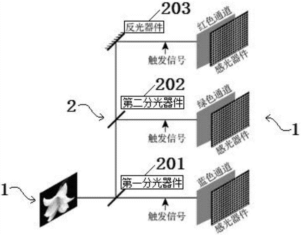
[0019] Such as figure 1 As shown, taking a 60Hz video source 1 as an example, a transflective light splitting device 2 is provided between the video source 1 and the photosensitive device 3, and the light splitting device 2 consists of a first light splitting device 201, a second light splitting device 202 and Reflective device 203, the image signal sent by video source 1 partly enters the blue channel through the first light-splitting device 201, partly reflects to the second light-splitting device 202, and the second light-splitting device 202 projects part of the image information into the color filter channel, Part of it is reflected on the light-reflecting device 203, and the light-reflecting device 203 reflects the image signal into the red channel again, and corresponding photosensitive devices 3 are arranged behind each monochromatic channel.

[0020] (2) Channel phase delay

[0021] In order to reduce the color splitting...

Embodiment 2

[0024] (1) Primary color channel separation

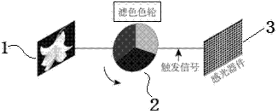
[0025] Such as figure 2 As shown, still taking the 60Hz video source 1 as an example, a color filter wheel is set between the video source 1 and the photosensitive device 3 as the primary color channel separation structure 2, and the color filter wheel is provided with three primary color filter modules, adjacent filter color The phase difference of the modules is 120°; during the rotation of the color filter wheel, the image signal sent by the video source 1 circulates through each primary color filter module to form a monochrome channel corresponding to each primary color, and the image information of the monochrome channel is recorded in On the photosensitive device 3;

[0026] (2) Channel phase delay

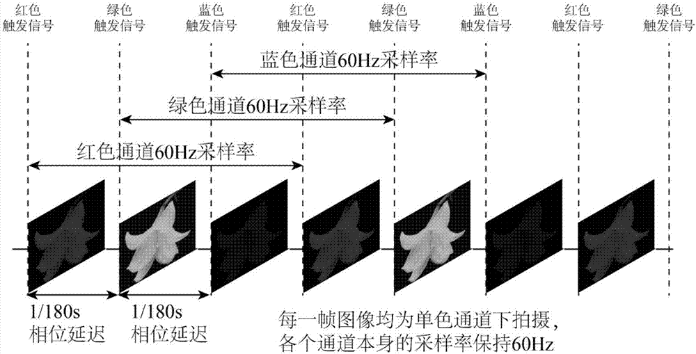
[0027] figure 2 The rotation speed of the middle filter color wheel is 60r / s, the sampling rate of the trigger signal of the monochrome channel is 180Hz, and the initial phase difference between the two is 0.

[0028] Both ...


PUM


Abstract

The invention discloses a field order display camera system based on motion compensation. The system comprises a video source, a three-primary color channel separating structure and a light-sensing device; an image signal of the video source enters a monochrome channel of three primary colors through the three-primary color separating structure, after the phase delay on each chrome channel, the corresponding monochrome image is acquired and stored by the light-sensing device; starting with the structure of a shooting system, a motion compensation shooting scheme specialized for the field order display is realized through the primary color channel separation and the phase delay; since the video shot by the camera system disclosed by the invention can directly match with the field order display corresponding to the refreshing rate, the required hardware sampling rate and the storage space are unchanged, the complicated frame insertion operation is unnecessary, and the additional equipment manufacturing cost is avoided.

Description

technical field [0001] The invention relates to a camera system, in particular to a camera system of a field sequential display based on motion compensation. Background technique [0002] Sequential color mixing display (FSC) achieves image color mixing by switching several primary color subfields at a refresh rate much higher than the limit fusion frequency (CFF) of the human eye, such as various projection devices. Compared with the spatial primary color sub-pixel color mixing method currently used by most liquid crystal displays, the sequential color mixing display does not require color filters. This structure will bring many advantages: (1) The manufacturing cost of the overall panel is reduced; (2) High light efficiency and low power consumption are very critical in extreme display application scenarios, such as commercial displays; (3) Increase the resolution by 3 times without changing the existing panel manufacturing process. Despite the above-mentioned advantages ...

Claims


Application Information

Patent Timeline
Patent Type & Authority Applications(China)
IPC IPC(8): H04N5/222
CPCH04N5/222
Inventor 张宇宁王坚翁一士
Owner SOUTHEAST UNIV
Learn More