AI technical title is built by PatSnap AI team. It summarizes the technical point description of the patent document.
A technology for placing devices and traffic cones, applied in traffic signals, roads, buildings, etc., can solve the problem of inconvenient placement of traffic cones
Active Publication Date: 2019-10-11
SHANDONG JIANZHU UNIV
View PDF6 Cites 0 Cited by
Summary
Abstract
Description
Claims
Application Information
AI Technical Summary
This helps you quickly interpret patents by identifying the three key elements:
Problems solved by technology
Method used
Benefits of technology
Problems solved by technology
[0003] In order to achieve the purpose of the above invention, and aiming at the problem of inconvenient placing of traffic cones, the present invention provides a device for placing traffic cones
Method used
Image
Click on the blue label to locate the original text in one second.
Reading with bidirectional positioning of images and text.
Examples
Embodiment 1
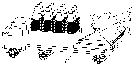
[0026] see Figure 1 to Figure 3 , the present invention provides a traffic cone placement device, comprising a truck body, and a truck body arranged at the rear of the truck body, and a traffic cone placement unit 1 is arranged on the rear side of the truck body;
[0027] The traffic cone placement unit 1 includes a base 2 and a traffic cone placement mechanism 4, the base 2 is connected to the rear of the truck body through rails, the base 2 is provided with a telescopic push rod 3, and one end of the telescopic push rod 3 is fixed to the base 2 connected, and the other end is fixedly connected to the lower surface of the traffic cone placement mechanism 4;
[0028] The traffic cone input port is reserved on the front side of the traffic cone placement mechanism 4, and the traffic cone exit is set on the rear side. The rear lower edge of the traffic cone placement mechanism 4 is hinged with the rear edge of the base 2; the traffic cone placement mechanism 4 The upper surfac...
Embodiment 2
[0043] On the basis of Embodiment 1, the rear side of the traffic cone channel 402 can be provided with a slide rail, and the slide rail extends to a position closer to the ground, and the auxiliary traffic cone slides down along the slide rail.
Embodiment 3
[0045] The difference from Embodiment 1 is that the downward movement of the traffic cone group is assisted by a vibrating mechanism.
[0046] A traffic cone placement device, comprising a truck body, and a truck body arranged at the rear of the truck body, and a traffic cone placement unit 1 is arranged on the rear side of the truck body;
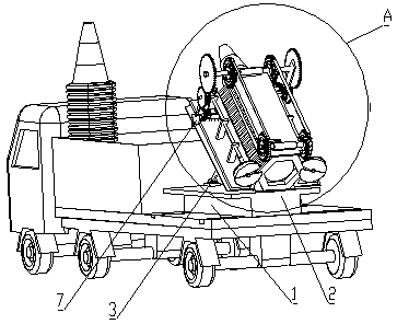
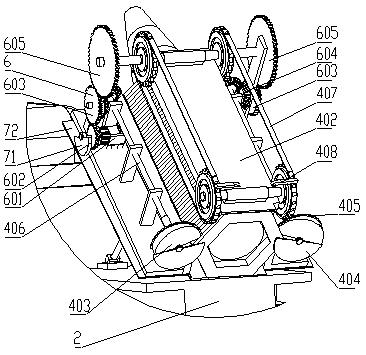
[0047] The traffic cone placement unit 1 includes a base 2, a traffic cone placement mechanism 4 and a vibration mechanism 7, the base 2 is connected to the rear of the truck body through rails; the base 2 is provided with a telescopic push rod 3, and the telescopic push rod 3 One end is fixedly connected to the bottom platform 2, and the other end is fixedly connected to the lower surface of the vibration mechanism 7; the traffic cone placement framework 4 is arranged on the vibration mechanism 7; side edge hinged;
[0048] The front side of the traffic cone placement mechanism 4 reserves a traffic cone input port, and the rear side is p...
PUM
Abstract
The invention discloses a traffic cone placing device and relates to the field of road traffic equipment. According to the technical scheme, the traffic cone placing device comprises a truck body and a truck bucket arranged on the rear portion of the truck body; a traffic cone placing unit is arranged on the rear side of the truck bucket and comprises a bottom platform and a traffic cone placing mechanism; the bottom platform is connected with the rear portion of the truck body through a rail; a telescopic pushing rod is arranged on the bottom platform; and one end of the telescopic pushing rod is fixedly connected with the bottom platform, and the other end of the telescopic pushing rod is fixedly connected with the lower surface of the traffic cone placing mechanism. A solar charging panel is arranged on the upper surface of a shell of the traffic cone placing mechanism, and the solar charging panel supplies power to the traffic cone placing mechanism through a storage battery. The traffic cone placing device has the beneficial effects that the traffic cone structure used in the traffic cone placing device is basically similar to the structure of an existing traffic cone, simple and easy to manufacture, the traffic cone placing unit and a truck are assembled together through a truck-mounted type structure, and in placing, traffic cones can be automatically placed in the advancing process of the truck only by additionally placing stacked traffic sets into the traffic cone placing device by people.
Description
technical field [0001] The invention relates to the field of road traffic equipment, in particular to a traffic cone placement device. Background technique [0002] Expressway is an important way of intercity traffic. When it needs to be repaired, in order to ensure that it still has a certain traffic capacity, it usually occupies a part of the adjacent reverse lane. In order to temporarily separate the lanes, it usually needs to be placed A large number of traffic cones are used to separate lanes by placing traffic cones at long distances. However, there is no device for effectively placing traffic cones at present, and the entire journey is very long by manually placing them. Contents of the invention [0003] In order to achieve the purpose of the above invention and to solve the problem of inconvenient placement of traffic cones, the present invention provides a device for placing traffic cones. [0004] The technical solution is to separate and place the superimpose...
Claims
Application Information
Patent Timeline
Application Date:The date an application was filed.
Publication Date:The date a patent or application was officially published.
First Publication Date:The earliest publication date of a patent with the same application number.
Issue Date:Publication date of the patent grant document.
PCT Entry Date:The Entry date of PCT National Phase.
Estimated Expiry Date:The statutory expiry date of a patent right according to the Patent Law, and it is the longest term of protection that the patent right can achieve without the termination of the patent right due to other reasons(Term extension factor has been taken into account ).
Invalid Date:Actual expiry date is based on effective date or publication date of legal transaction data of invalid patent.

