
Hydraulic motion system

A motion system and hydraulic technology, applied in the field of hydraulics, can solve problems such as labor and labor, and achieve the effects of clear principles, quick results, and easy popularization and promotion

Inactive Publication Date: 2018-12-11
张金强
View PDF0 Cites 0 Cited by
  • Summary
  • Abstract
  • Description
  • Claims
  • Application Information

AI Technical Summary

Problems solved by technology

Afterwards, human beings followed the old-fashioned way when applying the principle of leverage, and they still failed to break through the limitations of labor-saving and distance-saving. So far, the technology of using the principle of leverage to develop hydraulic circulation movement is still blank.

Method used


Image

  • Hydraulic motion system
  • Hydraulic motion system
  • Hydraulic motion system

Examples


Embodiment Construction

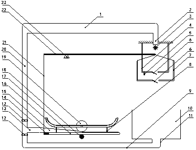
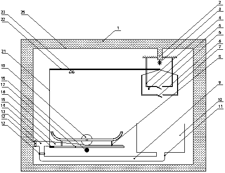
[0028] The hydraulic exercise system of the present invention will be further described in detail below in conjunction with the above-mentioned accompanying drawings.

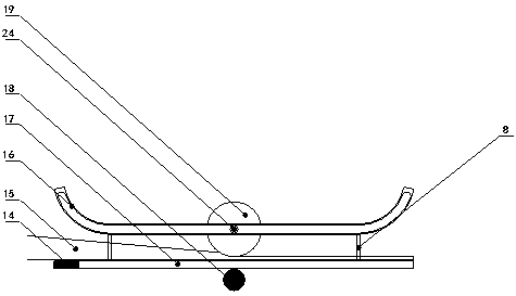
[0029] In the hydraulic exercise system of the present invention, the hose 15 is sandwiched between the seesaw 17 and the roller 19 .

[0030] The hydraulic motion system of the present invention has two kinds of land type and submerged type:

[0031] A. Land type: One end of the hose 15 is sealed with a broken end, the other end is connected to the return pipe 20 and the lower pipe 9 through the three-way fitting 13, and one end of the lower pipe 9 is connected to the return pipe 20 and the hose 15 through the three-way fitting 13, and the other One end is connected with the low-level pool 10, one end of the return pipe 20 is connected with the water belt 15 and the low-level pipe 9 through the three-way fitting 13, and one end is connected with the high-level pool 1, and the high-level pool 1 is connected wit...


PUM


Abstract

Disclosed is a hydraulic motion system. A water belt is sandwiched between a seesaw and a roller. One end of the water belt is broken and sealed, and the other end is connected to a reflux pipe and alower pipe through a three-way pipe fitting. One end of the lower pipe is connected to the three-way pipe fitting, and the other end is connected to a lower water tank. One end of the reflux pipe is connected to the three-way pipe fitting, and the other end is connected to a higher water tank. The higher water tank is connected to a flow guide pipe. A water storage tank is arranged under the flowguide pipe. A water container is arranged under the water storage tank. The lower water tank is arranged under the water container. The water container is connected to the seesaw through a lever. Theseesaw is connected to the lever trough a connecting piece, and a pressure balance member is arranged on the connected end. The weight of the pressure balance member is greater than the weight of theroller. The other end is in the same direction as the broken and sealed end of the water belt. The seesaw is a balance lever with a fulcrum in the middle. The hydraulic motion system has the advantages of clear principle, peculiar conception and extremely little mechanical friction. The seesaw and the roller can complete long-distance movement with only one-time effort. Furthermore, the hydraulicmotion system has the advantages of simple structure and manufacturing, less investment, quick effect, and easy popularization.

Description

technical field [0001] The invention belongs to the field of hydraulic technology, in particular to a hydraulic cycle motion system. Background technique [0002] In the field of hydraulic power, it has long been known that people use the water drop to do work, but the water drop is only once, and it cannot be recycled. As early as more than a thousand years ago, the scientist Archimedes discovered the principle of leverage and said, "Give me a fulcrum, and I can move the earth." Since then, human beings have been conservative in the application of the principle of leverage, and have not been able to break through the limitations of saving effort and distance, and saving distance and effort. So far, the technology of using the principle of leverage to develop hydraulic circulation movement is still blank. Contents of the invention [0003] The purpose of the present invention is to address the above problems, to provide a hydraulic cycle motion system, which utilizes the ...

Claims


Application Information

Patent Timeline
Patent Type & Authority Applications(China)
IPC IPC(8): F03B13/00F03B11/00
CPCF03B11/00F03B13/00Y02E10/20Y02P70/50
Inventor 张金强
Owner 张金强
Learn More