Feeding machine capable of throwing bait for 360 degrees

A technology of a feeder and a bait box, which is applied to the field of 360-degree bait-casting feeders, can solve the problems of complex structure, limited bait-casting area, and large destructiveness of the discharging mechanism, and achieve the effect of large feeding area

Active Publication Date: 2015-07-22
SHANGHAI OCEAN UNIV
View PDF9 Cites 9 Cited by
  • Summary
  • Abstract
  • Description
  • Claims
  • Application Information

AI Technical Summary

Problems solved by technology

In addition, the discharge mechanism of the control box of some bait-throwing feeders is realized by the cooperation of electromagnetic and connecting rod mechanism. When the connecting rod encounters the limit position during continuous movement, it will produce impact, which is very destructive to the discharging mechanism.
Some feeding mechanisms for bait throwing use a flat plate to throw material inclined, so that the material thrown out can only be thrown in a fan-shaped area, which is only suitable for throwing bait into the pond on the shore
In addition, the material control mechanism is a spiral tube, and the particles of the bait range from a few millimeters to more than ten millimeters. The spiral tube for large materials is easy to block
All in all, the existing bait-throwing feeder not only has complex structure, frequent failures and limited bait-throwing area, but also has high cost of use.

Method used


Image

  • Feeding machine capable of throwing bait for 360 degrees
  • Feeding machine capable of throwing bait for 360 degrees
  • Feeding machine capable of throwing bait for 360 degrees

Examples


Embodiment Construction

[0027] The 360-degree bait throwing feeder of the present invention will be further described in detail below in conjunction with the accompanying drawings.

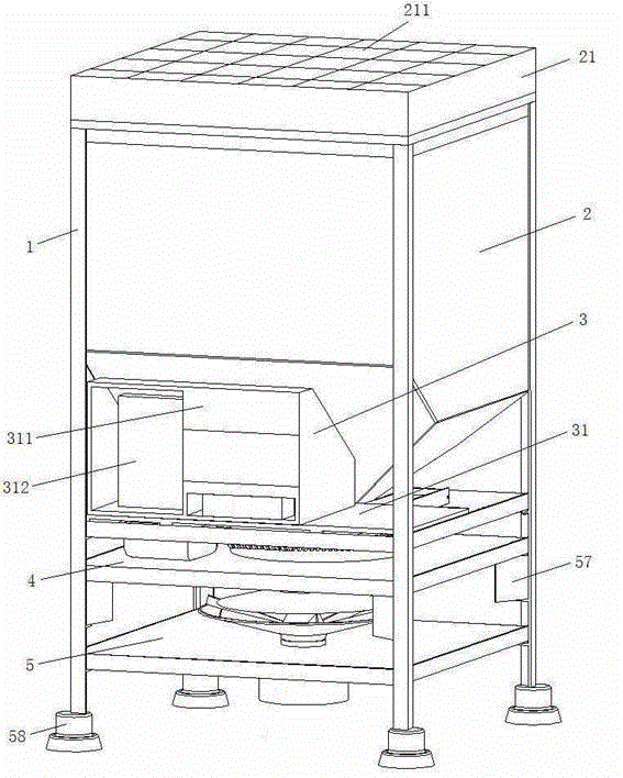
[0028] see figure 1 , figure 2 , image 3 , Figure 4 , Figure 5 , Figure 6 , Figure 7 , Figure 8 , Figure 9 and Figure 10 , the 360-degree bait-throwing feeder of the invention includes a frame 1, the frame 1 is a vertical cuboid frame formed by a vertical angle iron and a horizontal angle iron, and the described frame is formed by a vertical angle iron A foot suction cup 58 is respectively provided at the lower ends of the vertical angle irons of the vertical cuboid frame formed by the horizontal angle irons.

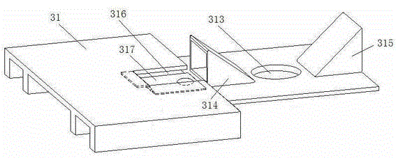
[0029] A bait box 2, a control box 3, a feed box 4 and a bait throwing layer 5 are successively established in the frame 1 from top to bottom.

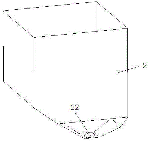
[0030] One side of the upper port of the bait box 2 is spliced ​​to connect an upper cover 21 with a solar panel 211 on the upper end surface, the lowe...


PUM


Abstract

A feeding machine capable of throwing bait for 360 degrees comprises a rack. A bait box, a control box, a feeding box and a bait throwing layer are arranged in the rack in sequence from top to bottom, one side of the upper port of the bait box is hinged to an upper cover with a solar cell panel, the lower end of the bait box is a hopper shaped like an inverted trapezoid, a discharge port is formed in the bottom of the bait box, a base plate of the control box is shaped like a ladder, a control box body and a storage battery are arranged on the high-end of the base plate of the control box, the low-end of the base plate of the control box is provided with an upper discharging hole, a left bait box supporting seat and a right bait box supporting seat, a mounting hole with a bait pressing spring piece is formed in the high-end, a circular groove is formed in the upper end face of a feeding box base plate of the feeding box, the inner bottom face of the groove is provided with a center hole with an inner thread, a lower discharging hole and a feeding plate, the upper end face of the feeding box base plate is further provided with a feeding plate electric motor, an output shaft of the feeding plate electric motor is provided with a worm, a lower discharging pipe and a bait throwing plate cover are arranged on the portion which is distributed with inner thread holes in the lower end face near the lower discharging hole, an assembly hole is formed in the upper end face of a bait throwing layer base plate of the bait throwing layer, the lower end face of the bait throwing layer base plate is provided with a bait throwing plate electric motor, and an output shaft of the bait throwing plate electric motor is provided with a bearing and a bait throwing plate in series. The feeding machine capable of throwing the bait for 360 degrees is suitable for throwing the bait in large areas of water.

Description

technical field [0001] The invention relates to a bait-throwing feeder, in particular to a 360-degree bait-thrower feeder. Background technique [0002] At present, a bait-throwing feeder placed on the shore is usually used more frequently, but the bait-throwing range of this bait-throwing feeder is greatly limited. In relatively large ponds or reservoirs, it is necessary to install a lot of shore bait-throwing feeders to meet the needs. In addition, the discharge mechanism of the control box of some bait-throwing feeders is realized by the cooperation of electromagnetic and connecting rod mechanism. When the connecting rod encounters an extreme position during continuous movement, it will produce impact, which is very destructive to the discharge mechanism. Some bait-throwing feeding mechanisms use a flat plate to throw material tiltedly, so that the thrown material can only be thrown into a fan-shaped area, which is only suitable for throwing bait into ponds on the shore....

Claims


Application Information

Patent Timeline
Patent Type & Authority Applications(China)
IPC IPC(8): A01K61/02
CPCY02A40/81Y02P60/60
Inventor 张丽珍马迪红胡庆松王江涛杨佺柏春祥
Owner SHANGHAI OCEAN UNIV
Why Eureka
Try Eureka