Mission-adaptive rotor blade

a technology of rotor blades and rotor blades, which is applied in the direction of rotors, marine propulsion, vessel construction, etc., can solve the problems of large moments at the hub and inefficient aerodynamics, and achieve the effects of accurate control, increased centrifugal force, and increased angle of attack

Active Publication Date: 2012-06-21
SKYWORKS GLOBAL INC +1
View PDF12 Cites 14 Cited by
  • Summary
  • Abstract
  • Description
  • Claims
  • Application Information

AI Technical Summary

Benefits of technology

[0035]One may think of the twist being the result of fibers wrapped around the blade and trying to unravel when acted on by a centrifugal force, much like the behavior of a tension-torsion spring. By controlling the placement and direction of the fibers, twist along the span of the blade may be accurately controlled.
[0036]In selected embodiments, fibers proximate the root of a rotor blade may be preferentially oriented to increase the angle of attack with increases in centrifugal force. Conversely, fibers proximate the tip of the rotor blade may be preferentially oriented to decrease the angle of attack with increases in the centrifugal force. Such embodiments may improve jump takeoff performance.

Problems solved by technology

This is aerodynamically inefficient and, depending on the type of rotor, can generate large moments at the hub.

Method used


Image

  • Mission-adaptive rotor blade
  • Mission-adaptive rotor blade
  • Mission-adaptive rotor blade

Examples


Embodiment Construction

[0056]It will be readily understood that the components of the present invention, as generally described and illustrated in the drawings herein, could be arranged and designed in a wide variety of different configurations. Thus, the following more detailed description of the embodiments of the system and method of the present invention, as represented in the drawings, is not intended to limit the scope of the invention, as claimed, but is merely representative of various embodiments of the invention. The illustrated embodiments of the invention will be best understood by reference to the drawings, wherein like parts are designated by like numerals throughout.

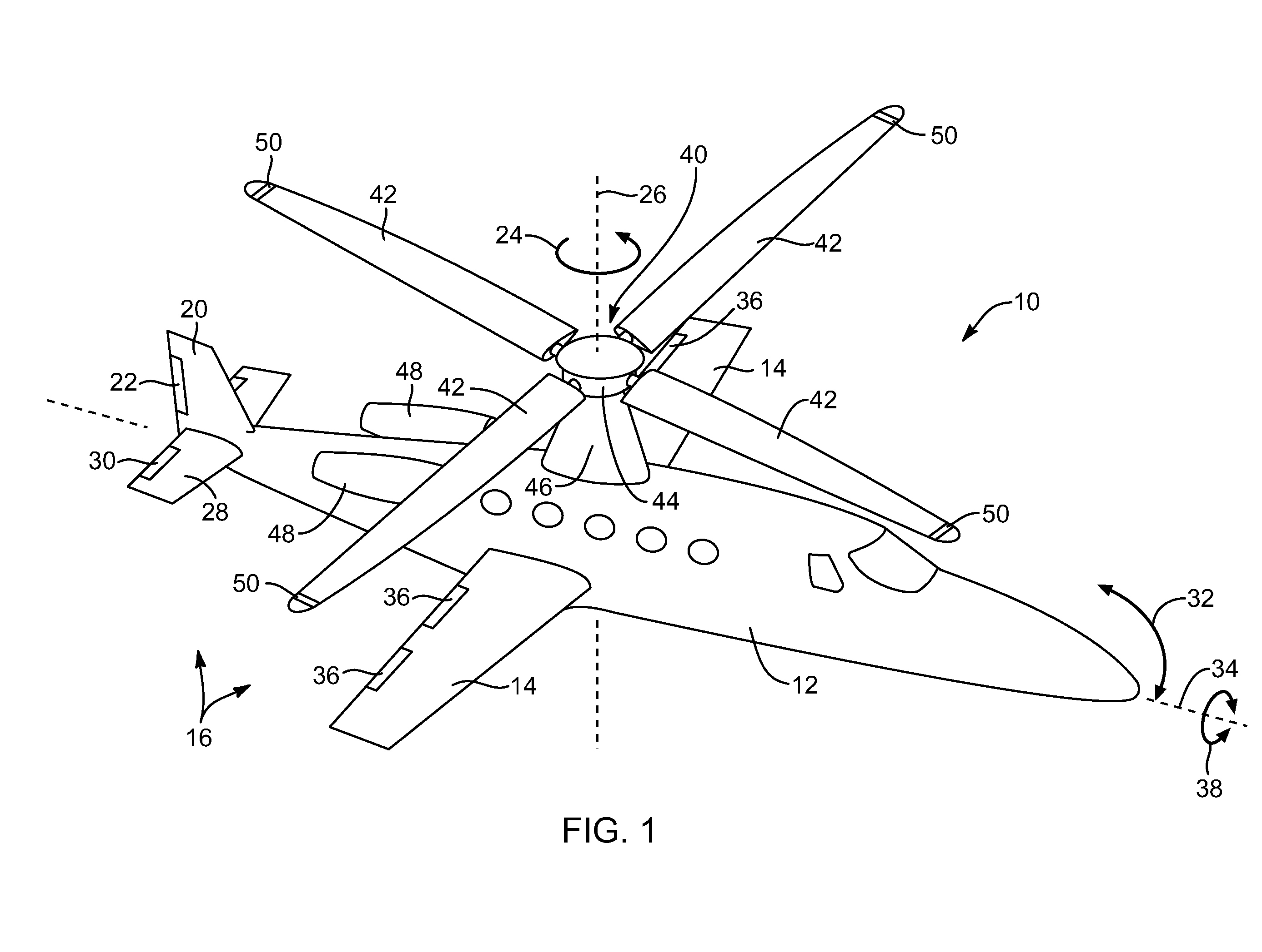
[0057]Referring to FIG. 1, a rotorcraft 10 in accordance with the present invention may include an airframe 12 defining a cabin for carrying an operator, passengers, cargo, or the like. The airframe 12 may include one or more fixed wings 14 or airfoils 14 providing lift to the rotorcraft 10. The wings 14 may be configured such t...


PUM


Abstract

A rotorcraft may include an airframe and a rotor connected to the airframe. The rotor may include a hub and a rotor blade connected to the hub to extend radially away therefrom. The rotor blade may include biasing fibers, oriented to increase the twist of the rotor blade in response to an increase in the speed of rotation of the rotor corresponding to a mission, task, or maneuver.

Description

BACKGROUND[0001]1. Related Applications[0002]This application claims the benefit of co-pending U.S. patent application Ser. No. 13 / 199,671, filed on Sep. 7, 2011, which claims the benefit of U.S. Provisional Patent Application Ser. No. 61 / 381,291, filed on Sep. 9, 2010, co-pending U.S. patent application Ser. No. 13 / 199,684, filed on Sep. 7, 2011,which claims the benefit of U.S. Provisional Patent Application Ser. No. 61 / 403,099, filed on Sep. 9, 2010, co-pending U.S. patent application Ser. No. 13 / 199,678, filed on Sep. 7, 2011, which claims the benefit of U.S. Provisional Patent Application Ser. No. 61 / 403,097, filed on Sep. 9, 2010, co-pending U.S. patent application Ser. No. 13 / 199,682, filed on Sep. 7, 2011, which claims the benefit of U.S. Provisional Patent Application Ser. No. 61 / 381,313, filed on Sep. 9, 2010, co-pending U.S. patent application Ser. No. 13 / 199,681, filed on Sep. 7, 2011, which claims the benefit of U.S. Provisional Patent Application Ser. No. 61 / 403,111, fi...

Claims


Application Information

Patent Timeline
Patent Type & Authority Applications(United States)
IPC IPC(8): B64C27/72B64C11/34
CPCB64C27/18B64C27/26B64C27/473B64C27/59B64C27/023B64C2027/4736B64C2027/7222Y02T50/34B64C27/008B64C27/72Y02T50/30
Inventor GROEN, DAVID L.
Owner SKYWORKS GLOBAL INC
Why Eureka
Try Eureka