Scroll compressor with crankshaft venting

a crankshaft and compressor technology, applied in the direction of machines/engines, rotary/oscillating piston pump components, liquid fuel engines, etc., can solve the problems of limited radial length of the various vent lines associated with such systems, affecting compressor lubrication, and affecting the lubrication of compressors, etc., to achieve the effect of enhancing the oil delivery

Active Publication Date: 2008-07-17
TRANE INT INC
View PDF18 Cites 15 Cited by
  • Summary
  • Abstract
  • Description
  • Claims
  • Application Information

AI Technical Summary

Benefits of technology

[0011]It is an object of the present invention to enhance the delivery of oil to various locations requiring lubrication in a scroll compressor.
[0012]It is a further object of the present invention to provide a system which facilitates the separation and removal of gas from lubricant as such lubricant is moved from the compressor sump to surfaces requiring lubrication.
[0014]One or more of the above listed objects of the present invention are provided by a scroll compressor the drive shaft of which includes an inclined lubricant gallery through which lubricant is delivered from the compressor sump. The shaft includes a vent arrangement the location and orientation of which is such that refrigerant traveling upward through the drive shaft with the compressor lubricant, which is in gaseous form or which comes to be in gaseous form in its travel, is capable of quickly being removed from critical locations in the lubricant flow path. The outlet of the vent arrangement is located beyond the nominal outside diameter of the drive shaft and takes advantage of the increased centrifugal force such location provides for. Further, oil retention locations are provided such that when the compressor shuts down, oil is retained in such locations. Those locations are adjacent surfaces that require lubrication such that when the compressor next starts up, retained oil is immediately flung onto such surfaces. As a result, an initial lubricant charge is provided to such locations prior to the arrival of a continuous lubricant stream which travels upward through the drive shaft to such locations from the compressor's oil sump subsequent to compressor start-up.

Problems solved by technology

Such vaporization or the conveyance of refrigerant gas into this area through the oil gallery can displace oil in a location where it is needed and / or otherwise adversely affect compressor lubrication.
For instance, the existence of too much vaporized refrigerant in this area can create a backpressure which operates against and reduces the flow of oil attempting to move upward through the drive shaft.
A common drawback of these systems is that the limited radial length of the various vent lines associated with such systems fail to take full advantage of centrifugal force that might otherwise be available to assist in lubricant flow.
Another problem related to the lubricant needs of scroll compressors at compressor start-up relates to the amount of time it may take for oil to make its way to various compressor systems that require lubrication.
If the amount of time it takes for such lubricant to reach such surfaces is too great, relatively dry bearing surfaces may be damaged before they become properly lubricated.
Although such systems may be effective, they can require additional parts or offer additional complexity that may increase a compressor's reliability and / or increase its cost.

Method used


Image

  • Scroll compressor with crankshaft venting
  • Scroll compressor with crankshaft venting
  • Scroll compressor with crankshaft venting

Examples


Embodiment Construction

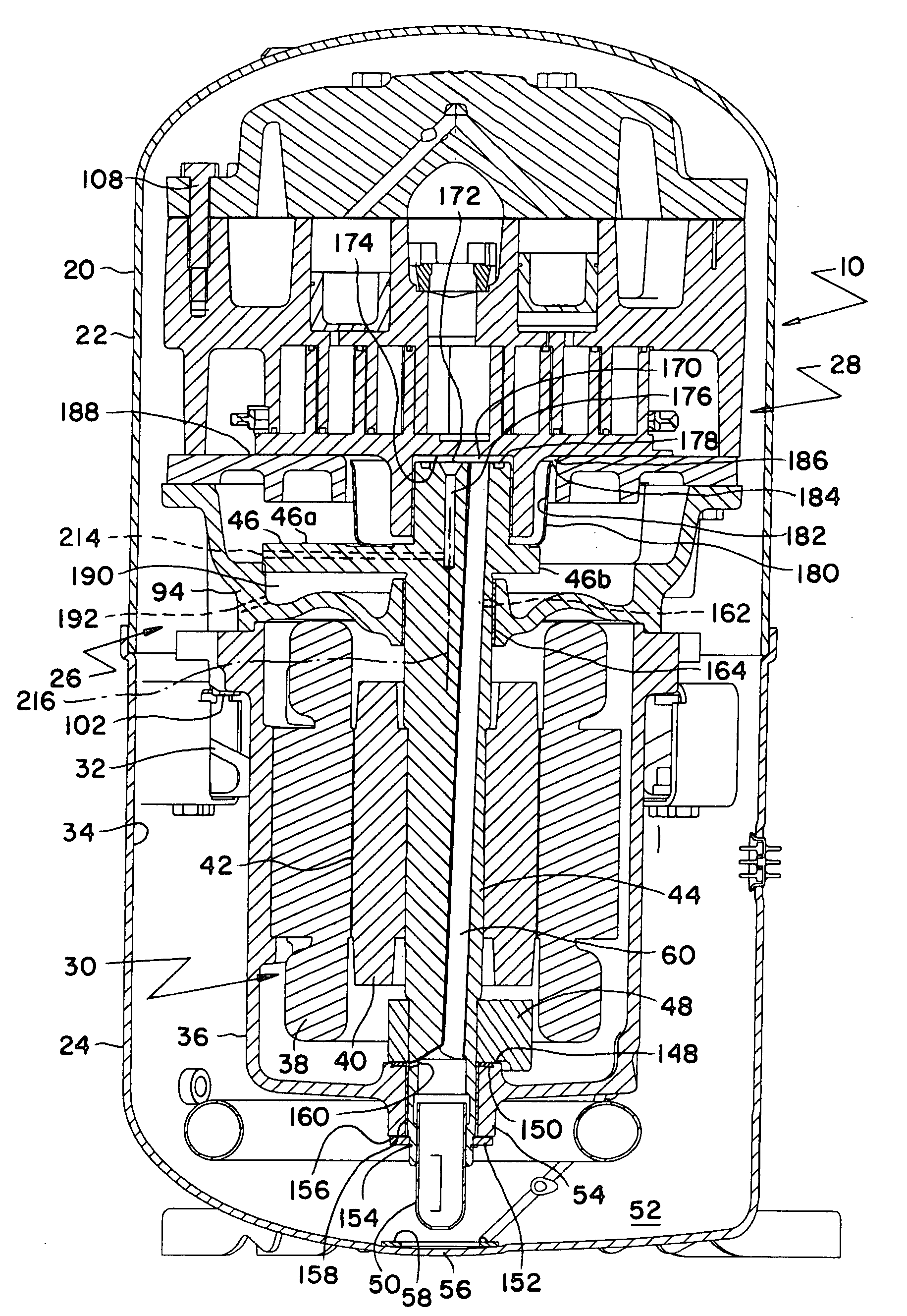
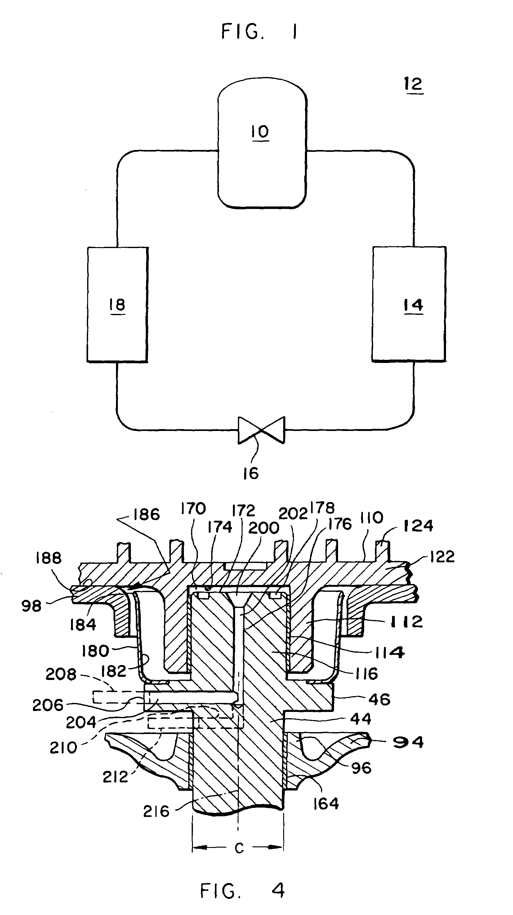
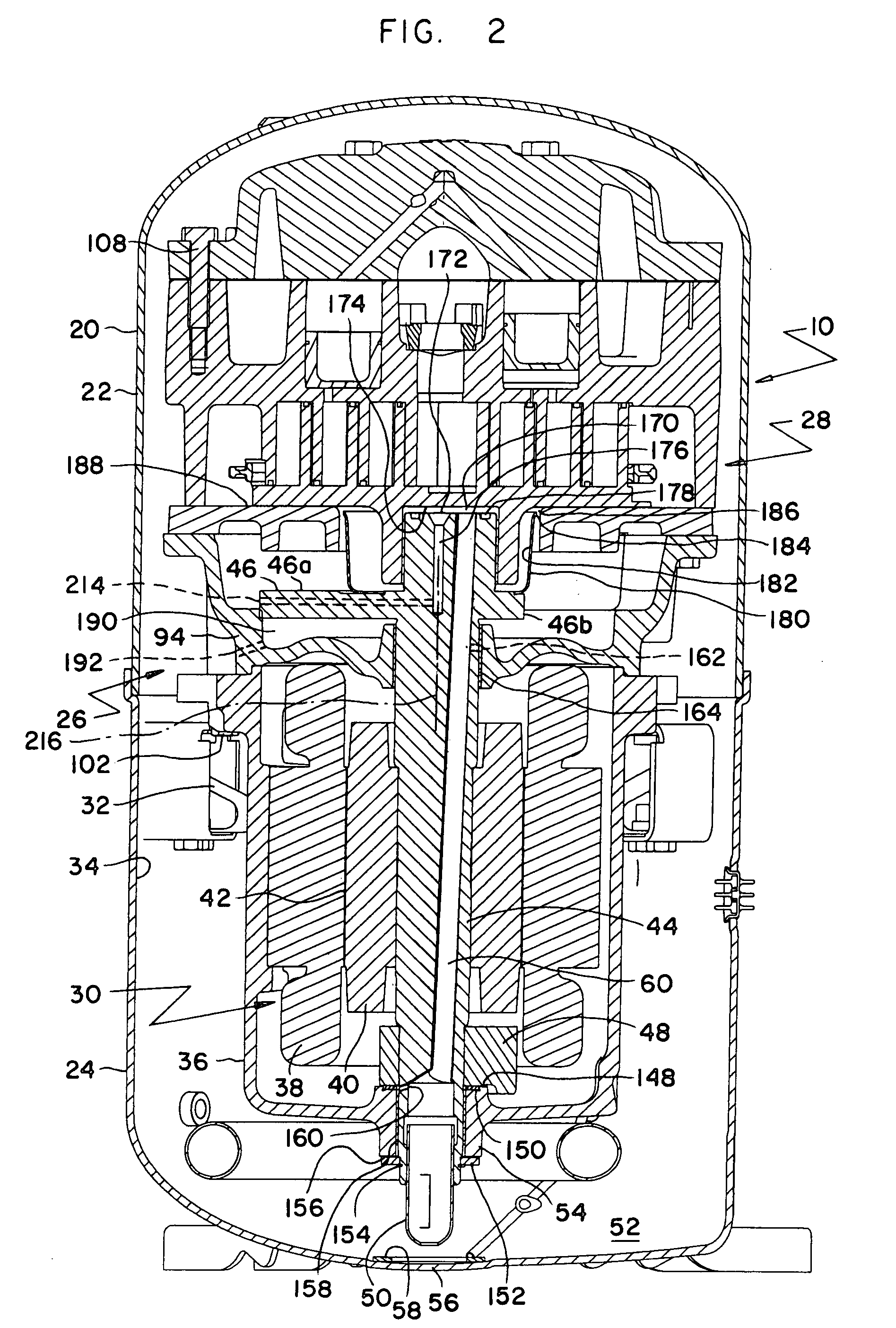
[0021]Referring initially to FIGS. 1 and 2, scroll compressor 10 of the present invention is, in its preferred embodiment, designed for use in a refrigeration system 12 the primary components of which are compressor 10, condenser 14, expansion device 16 and evaporator 18. Although illustrated as a cooling only system, refrigeration system 12 may be a cooling only system or a heat pump system, the fundamental operation of both of which are well known. As is also well known, such systems can be employed to cool or heat liquid or air. When used to cool a liquid, system 12 is typically referred to as a liquid chiller. When used to cool and / or heat air, system 12 would typically be referred to as an air conditioner or heat pump.

[0022]Irrespective of its specific nature, system 12 will employ a refrigerant, such as, for example, one of the refrigerants commonly referred to as R-134a, R407C, R410A or R-22. In operation, the refrigerant in system 12 is drawn from evaporator 18 by compressor...


PUM


Abstract

Lubrication of bearing surfaces in a scroll compressor is enhanced by a vent arrangement which makes use of increased centrifugal force, achieved by locating the outlet of the vent arrangement radially outside of the nominal circumference of the compressor's drive shaft, to both remove refrigerant gas from compressor locations where such gas can inhibit the flow and delivery of lubricant to such surfaces and to increase the lift of lubricant out of the compressor's lubricant sump. Oil retained in the upper surface of the compressor drive shaft is made immediately available for bearing lubrication upon compressor start-up to further enhance compressor lubrication.

Description

CROSS-REFERENCE TO RELATED APPLICATIONS[0001]This is a continuation of application Ser. No. 11 / 170,448, filed Jun. 29, 2005.BACKGROUND OF THE INVENTION[0002]1. Field of the Invention[0003]The present invention relates to a scroll compressor. More specifically, the present invention relates to a scroll compressor having enhanced lubrication by the employment of one or both of a vent arrangement and oil retention features that facilitate oil delivery at compressor start-up and during compressor operation.[0004]2. Description of the Background Art[0005]Scroll compressors typically comprise two basic scroll members each with scroll wraps that interleave to create a series of compression chambers therebetween. Relative movement between the scroll members cyclically recreates such compression chambers at the outer periphery of the scroll members where suction gas enters thereinto. Those chambers close and decrease in volume as the relative orbital motion of the scroll members continues co...

Claims


Application Information

Patent Timeline
Patent Type & Authority Applications(United States)
IPC IPC(8): F04C15/00F04C2/02F04C29/02F04C29/00F04C18/02
CPCF04C18/0215F04C23/008F04C2240/50F04C29/0057F04C29/023F04C28/06
Inventor EBER, ALAN HVCRUM, DANIEL R.
Owner TRANE INT INC
Why Eureka
Try Eureka