Crank shaft of refrigeration compressor

A technology for refrigeration compressors and crankshafts, which is applied to mechanical equipment, machines/engines, and liquid variable displacement machinery, etc. It can solve problems such as reduced lubrication performance and cooling performance, unsmooth supply of refrigeration oil, and inability to supply refrigeration oil in time. Achieve high centrifugal force and prevent refrigeration oil leakage

Inactive Publication Date: 2003-07-02
LG ELECTRONICS (TIANJIN) APPLIANCES CO LTD
View PDF0 Cites 15 Cited by
  • Summary
  • Abstract
  • Description
  • Claims
  • Application Information

AI Technical Summary

Problems solved by technology

[0009] However, the above-mentioned crankshaft 20 is mainly made for high-speed operation. When it is operated at a low speed, the oil supply of the refrigerating machine oil will not be smooth, that is, the refrigerating machine oil L will move upward due to the centrifugal force generated by the rotation of the crankshaft 20.
When the crankshaft rotates at a low speed, due to the sharp decrease in centrifugal force, the refrigeration oil cannot be supplied in time, and the lubrication performance to prevent friction of various parts and the cooling performance to dissipate internal heat to the outside will be reduced, which is fatal to the life of the compressor.

Method used


Image

  • Crank shaft of refrigeration compressor
  • Crank shaft of refrigeration compressor
  • Crank shaft of refrigeration compressor

Examples


Embodiment 1

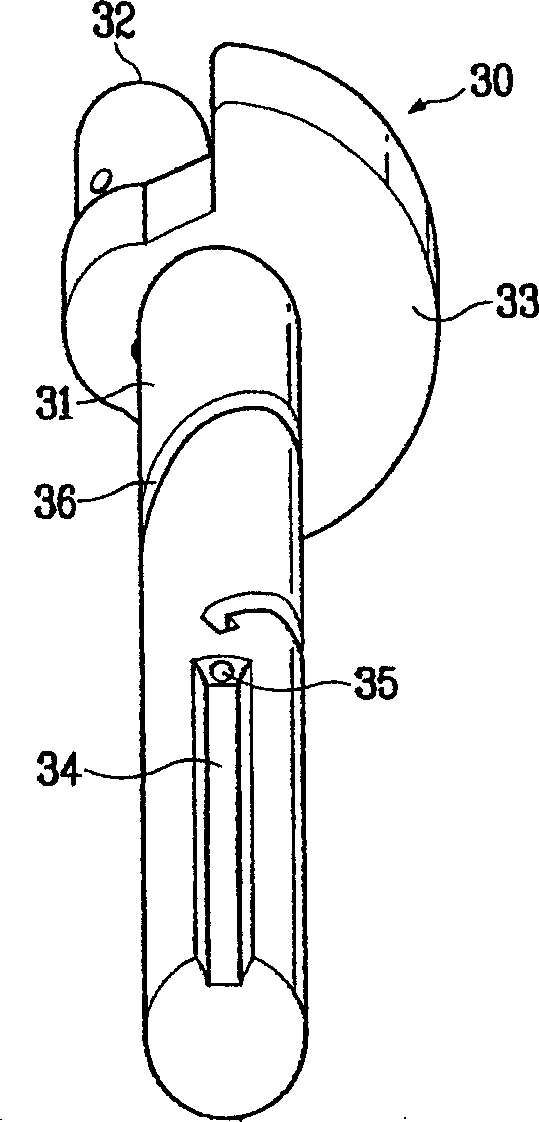
[0035] Such as Figure 4 The crankshaft shown is a form in which an oil pump is directly coupled to the lower end of the shaft. Such as Figure 4 As shown, the oil pump is composed of a hollow cylindrical plunger 37a inserted into the peripheral surface of the lower end of the shaft, and a thruster 37b obliquely provided inside the plunger to form a refrigerating machine oil ascending oil passage, and rotates on the shaft 31. A centrifugal oil pump that pumps out the refrigerating machine oil by the centrifugal force generated during the operation.

[0036]First, when power is supplied to the motor to rotate the rotor, the shaft portion 31 pressed into the rotor rotates accordingly. At this time, the refrigerating machine oil rises up by the propeller 37b of the oil pump by the centrifugal force and flows into the first oil groove 34 of the shaft. Next, the refrigerating machine oil rises through the oil passage between the first oil tank 34 and the rotor, and flows into th...

Embodiment 2

[0039] Figure 5 In the crankshaft shown, the oil pump is not directly connected to the shaft, but inserted into the lower end of the rotor.

[0040] Such as Figure 5 As shown, the plunger 47a of the above-mentioned oil pump is inserted into the lower end of the rotor 5 by a predetermined length, and the plunger 47a is separated from the lower end of the shaft portion 31 by a predetermined interval. At this time, there is no problem even if the plunger 47a is tangent to the shaft portion 31 . In this case, an O-ring should be provided between the plunger 47a and the rotor 5 in order to prevent oil leakage of the refrigerating machine.

[0041] When electricity is applied and the electric part rotates the rotor, the shaft part 31 rotates together with the oil pump. At this time, the refrigerating machine oil rises under the action of the propeller 47b of the oil pump by centrifugal force and flows into the first oil groove 34 of the shaft portion, and the subsequent functio...


PUM


Abstract

A crankshaft of refrigerating compressor features that a channel of cooling machine oil is formed along the circumference in order to raise the cooling machine oil up by a centrifugal force. It is composed of a solid cylindrical shaft inserted in rotor and bearing, an eccentrical part communicated with the said channel of cooling oil, and an oil pump for pumping oil to the said channel. Its advantages are supplying cooling oil even at low speed and no leakage of cooling oil.

Description

technical field [0001] The invention relates to the field of mechanical oil circuit transmission, in particular to an oil supply structure capable of supplying sufficient refrigerating machine oil when the crankshaft of a compressor is running at a low speed. Background technique [0002] Generally speaking, refrigeration compressors are used in refrigeration control devices such as refrigerators and air conditioners to compress the working oil that passes through the evaporation heat exchanger and supply it to the condensation heat exchanger. [0003] Hereinafter, general refrigeration compressors and their crankshafts, particularly reciprocating compressors and their crankshafts, will be described with reference to the accompanying drawings. [0004] first, figure 1 A cross-sectional view of a general refrigeration compressor; figure 2 It is a front view of the crankshaft of a general refrigeration compressor. [0005] Such as figure 1 As shown, the reciprocating comp...

Claims


Application Information

Patent Timeline
Patent Type & Authority Applications(China)
IPC IPC(8): F04B39/02F04B39/06
Inventor 金敬皓金碁柱卢铁基
Owner LG ELECTRONICS (TIANJIN) APPLIANCES CO LTD
Why Eureka
Try Eureka