
Radial spray regular cyclone separator
A cyclone separator and separation chamber technology, which is applied in cyclone devices, devices whose axial directions of cyclones can be reversed, etc., can solve problems such as additional energy consumption, and achieve increased speed, centrifugal force, and centrifugal separation force. Effect
- Summary
- Abstract
- Description
- Claims
- Application Information
AI Technical Summary
Problems solved by technology
Method used
Image

Examples
Embodiment Construction
[0019] specific implementation plan
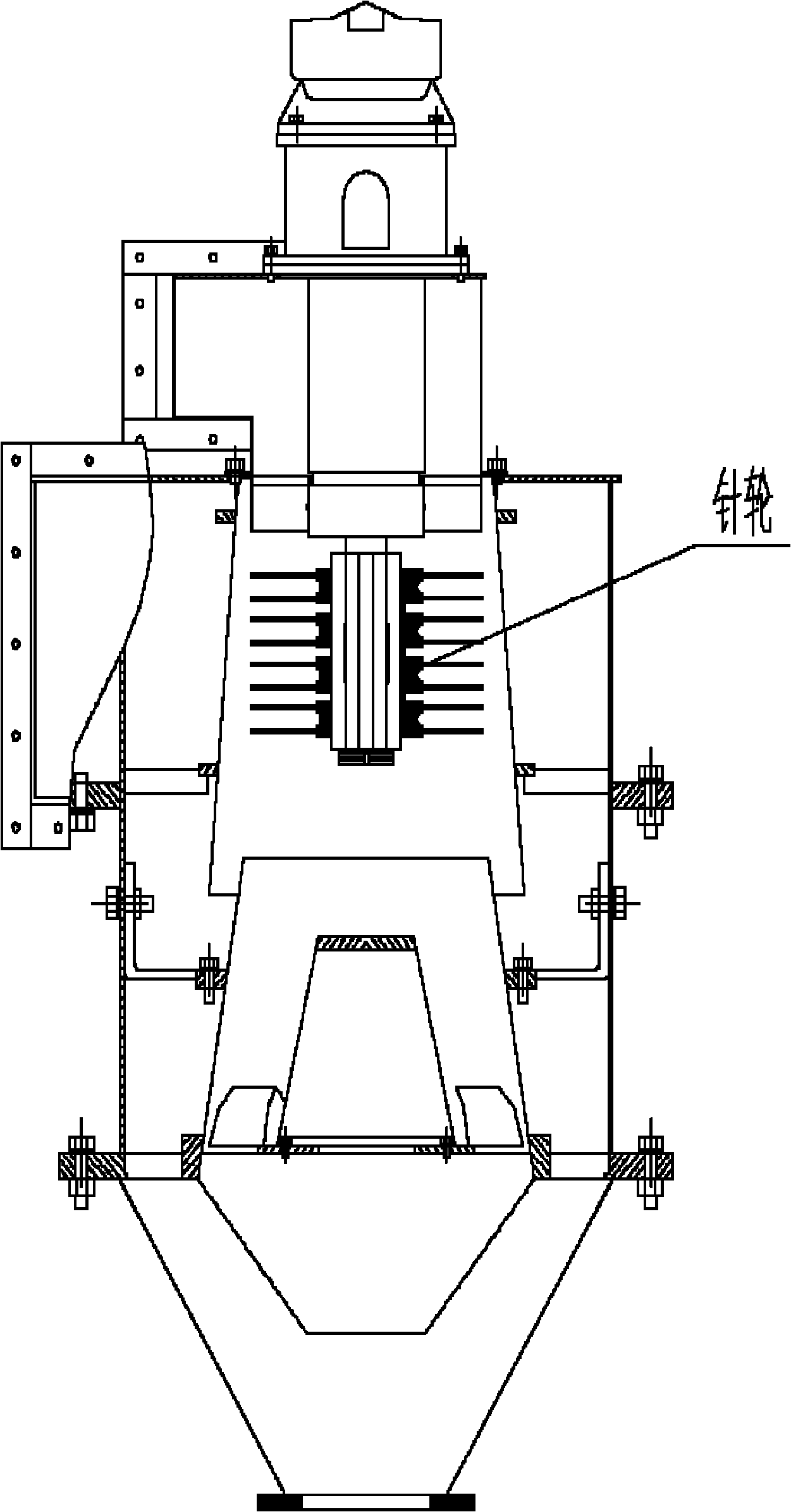
[0020] Radial jet structured cyclone separator (such as Figure 4 As shown), a radial impeller 4 is fixed on the top of a spiral flow separation outdoor cylinder 6 installed vertically on the axis, and the axis of the radial impeller 4 coincides with the axis of the outer cylinder 6 . An inner cylinder 7 is coaxially installed in the outer cylinder 6, and two concentric cylinders with different diameters form a spiral flow separation chamber 8. The uppermost end of the inner cylinder 7 is fixed on the disc of the radial impeller 4 . On the top of the spiral flow separation chamber 8, a group of spiral guide vanes 5 are evenly installed in the circumferential direction, and the uppermost end of each spiral guide vane 5 is fixedly connected with the blades of the radial impeller 4 respectively, and is respectively connected with the spiral flow separation chamber 8. The outer cylinder and inner cylinder correspond to close contact. The pu...
PUM
 Abstract
Description
Claims
Application Information