Lubrication structure for rolling bearing

a technology of lubrication structure and rolling bearing, which is applied in the direction of pressure lubrication, mechanical equipment, machines/engines, etc., can solve the problems of inability to generate adequate oil supply pressure, interfere with further lubrication oil supply, and inability to smoothly supply lubrication oil to the inside of the bearing, etc., to improve the cooling effect of the bearing, reduce the rotational speed difference, and increase the oil quantity

Inactive Publication Date: 2006-07-04
IHI CORP
View PDF9 Cites 15 Cited by
  • Summary
  • Abstract
  • Description
  • Claims
  • Application Information

AI Technical Summary

Benefits of technology

[0009]The present invention was made to solve the above-mentioned problems. It is a first object of the present invention to enhance a cooling effect of a bearing by decreasing a rotational speed difference between an oil accumulating room and lubrication oil, and thereby increasing an oil quantity actually used for the bearing lubrication. Further, it is a second object of the present invention to provide a bearing lubrication structure that makes it easy to estimate a supplying quantity of lubrication oil and that improves accuracy in prediction of the lubrication oil quantity actually used for the bearing lubrication.
[0016]By this structure of the present invention, the fin member installed in the oil accumulating room causes the lubrication oil in the oil accumulating room to follow the rotation of the oil accumulating room so that the lubrication oil can be forcibly rotated. Accordingly, a rotational speed difference between the oil accumulating room and the lubrication oil can be made small. Therefore, a centrifugal force applied on the lubrication oil can be increased, the lubrication oil quantity actually used for the bearing lubrication can be increased, and a cooling effect of the bearing can be enhanced.
[0018]By this structure, a forcible force that causes the lubrication oil to rotate can be increased, and a difference in the number of revolutions between the oil accumulating room and the lubrication oil can be effectively reduced. Therefore, a lubrication oil quantity actually used for the bearing lubrication can be increased, and a cooling effect of the bearing can be reliably enhanced. Further, in accordance with a rotational speed of the oil accumulating room, the centrifugal force of the lubrication oil is increased, and a supplying quantity of lubrication oil can be determined. Therefore, it becomes easy to estimate a supplying quantity of lubrication oil, and it is possible to improve accuracy in prediction of lubrication oil quantity that is actually used for the bearing lubrication.
[0020]By providing a plurality of fin members in the circumferential direction, the forcible force that causes the lubrication oil to rotate can be further increased, and the difference in the number of revolutions between the lubrication oil and the oil accumulating room can be further reduced. Therefore, the lubrication oil quantity actually used for the bearing lubrication can be further increased, and the cooling effect of the bearing can be further effectively improved. In addition, it is possible to further improve accuracy in prediction of the lubrication oil quantity actually used for the bearing lubrication.

Problems solved by technology

In addition, the rebounding lubrication oil interferes with further supplying of the lubrication oil 21.
Therefore, there is a problem in that the lubrication oil cannot be smoothly supplied to the inside of the bearing.
However, even in the lubrication means using the above-mentioned inner ring lubrication method, there is a rotational speed difference between the oil accumulating room 26 and the lubrication oil 21, so that an adequate oil supplying pressure cannot be generated.
For this reason, there is a problem in that there is a case where a sufficient quantity of lubrication oil actually used for the bearing lubrication cannot be obtained.
Furthermore, since the rotational speed difference between the oil accumulating room and the lubrication oil is unknown, it is difficult to estimate a supplying quantity of lubrication oil.
Therefore, there is a problem in that prediction of the lubrication oil quantity that is actually used for the bearing lubrication results in low accuracy.

Method used


Image

  • Lubrication structure for rolling bearing
  • Lubrication structure for rolling bearing
  • Lubrication structure for rolling bearing

Examples


embodied example

[Embodied Example]

[0033]In order to confirm advantages of the bearing lubrication structure according to the present invention, the following test was performed.

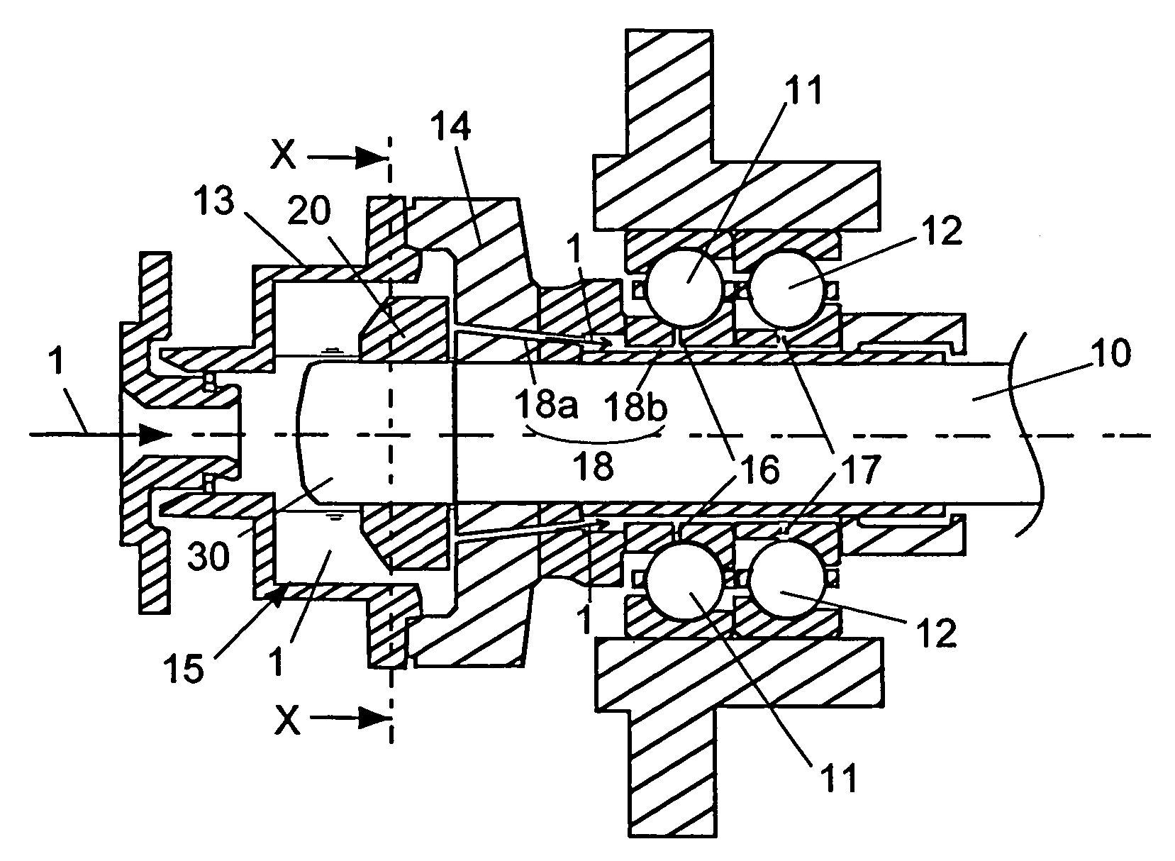
[0034]FIG. 3a is a sectional view showing an embodied example of the bearing lubrication structure according to the present invention. FIG. 3b is a cross sectional view taken along the line X—X in FIG. 3a. A bearing in this embodied example is applied to a supercharger for a boat, ship or vessel. In the drawings, the reference numeral 10 designates a shaft, 11 a four contact point ball bearing, 12 an angular ball bearing, 13 a cylindrical rotary cup having a cavity, and 14 a disk member. A space defined by the rotary cup 13, the disk member 14, and a shaft end nut 30 of the shaft 10 forms an oil accumulating room 15. The reference numerals 16 and 17 designate lubrication oil holes that supply the lubrication oil to the inside of the bearing and radially penetrate through the inner rings 11 and 12, respectively. The lubricati...


PUM


Abstract

A fin member is installed in an oil accumulating room. The fin member causes lubrication oil to follow rotation of the oil accumulating room so that the lubrication oil can be forcibly rotated. In this manner, a rotational speed difference between the oil accumulating room and the lubrication oil is made small, and an adequate oil supplying pressure is generated by the centrifugal force. As a result, a sufficient quantity of the lubrication oil can be supplied. Therefore, estimation of a supplying oil quantity becomes easy, and accuracy in prediction of the lubrication oil quantity actually used for the bearing lubrication can be improved.

Description

[0001]This application claims priority from Japanese Patent Application No. 171324 / 2003, filed Jun. 16, 2003, the entire disclosure of which is incorporated herein by reference.BACKGROUND OF THE INVENTION[0002]1. Field of the Invention[0003]The present invention relates to a lubrication structure for a rolling bearing that is used for high speed rotation.[0004]2. Description of the Related Art[0005]By supplying lubrication oil to a rolling bearing, the rolling bearing is lubricated and cooled. A jet injection method and an inner ring lubrication method are known as a general method of lubricating the rolling bearing. FIGS. 1a and 1b show conventional lubrication structures of the rolling bearing. FIG. 1a shows the jet injection method, and FIG. 1b shows the inner ring lubrication method. In the drawings, the rolling bearing includes an inner ring 22a, an outer ring 22b, a plurality of rolling elements 22c installed between the inner ring 22a and the outer ring 22c, retainers 22d ret...

Claims


Application Information

Patent Timeline
Patent Type & Authority Patents(United States)
IPC IPC(8): F16C33/66
CPCF16C33/6677F16C33/6651F16C2360/00F16C19/06F16C19/541
Inventor ITO, AKIRASATO, KIMITOSHIOSADA, YUKI
Owner IHI CORP
Why Eureka
Try Eureka