

Totally-Enclosed Fan-Cooled Motor
- Summary
- Abstract
- Description
- Claims
- Application Information
AI Technical Summary
Benefits of technology
Problems solved by technology
Method used
Image

Examples
first embodiment
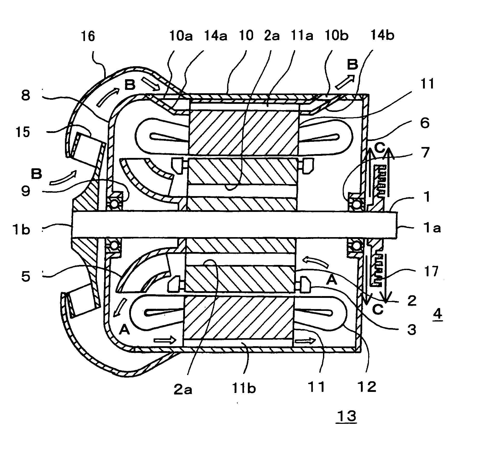
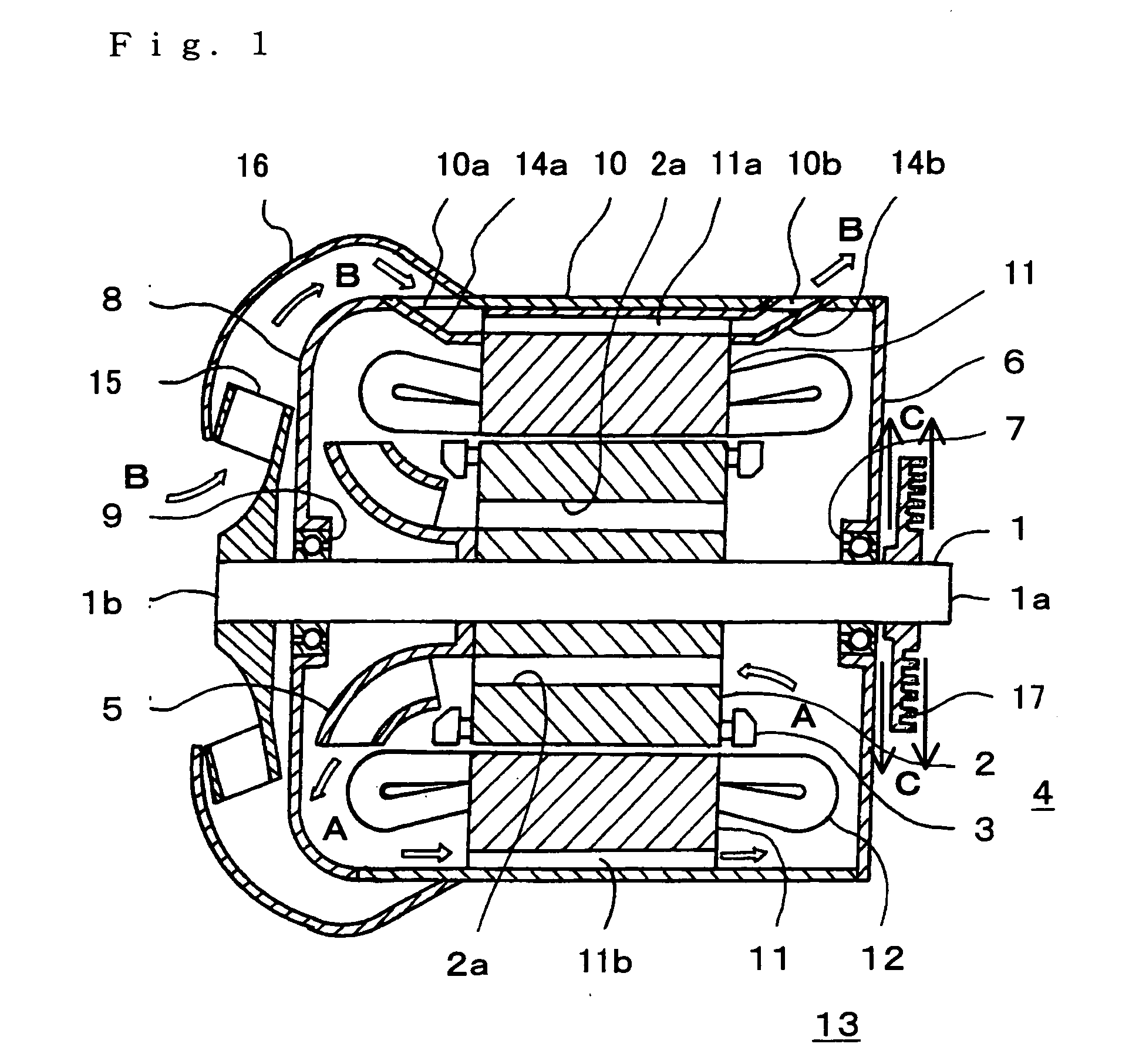
[0022]FIG. 1 is a sectional view of a totally-enclosed fan-cooled motor in a first embodiment for carrying out the invention. FIG. 2A is a front view of an integral part in FIG. 1. FIG. 2B is a sectional view taken away from a line II-II in FIG. 2A from a view in a direction shown by arrows. Same elements are marked with the same reference signs and numerals in FIGS. 1, 2A and 2B.
[0023] In FIGS. 1 and 2, a drive side 1a of a rotation shaft 1 is connected to a vehicle shaft (not shown) through reduction gear (not shown) in the case of a use for a vehicle, for example, so as to drive vehicle wheels (not shown) mounted to the vehicle shaft to run the vehicle. Plural ventilation paths 2a are formed in a circumferential direction in a rotor core 2 connected to the rotation shaft 1 into one body so as to pass through the rotor core 2 in an axial direction of the rotation shaft 1. A rotor conductor 3 is provided on an outer circumference of the rotation core 2. The rotor core 2 and the ro...
second embodiment
[0030]FIG. 3 is a sectional view of a totally-enclosed fan-cooled motor in a second embodiment for carrying out the invention. FIG. 4A is a front view of an integral part in FIG. 3. FIG. 4B is a sectional view taken away from a line IV-IV in FIG. 4A from a view in a direction shown by arrows. FIG. 4C is a back view. Same elements are marked with the same reference signs and numerals in FIGS. 3 and 4. Further, elements same as or equal to those in FIGS. 1 and 2 are marked with the same reference signs and numerals. The second embodiment of the invention will be described hereinafter mainly in a point different from the first embodiment of the invention. Description other than the different point will be omitted.
[0031] In FIGS. 3 and 4, the radiator 17 is connected to the rotation shaft 1 into one body on the outer side of the bearing 7 holding the drive side 1a of the rotation shaft 1, outside the motor and in the vicinity of the bearing 7. Similarly to the above-mentioned case of t...
third embodiment
[0033]FIG. 5 is a sectional view of a totally-enclosed fan-cooled motor in a third embodiment for carrying out the invention. In FIG. 5, elements same as or equal to those in FIGS. 1 to 4 are marked with the same reference signs and numerals. The third embodiment of the invention will be described hereinafter mainly in a point different from the first and second embodiments of the invention. Description other than the different point will be omitted.
[0034] In FIG. 5, provided is a wind direction guide 18 on a side opposite to the external fan 15 provided on the side 1b opposite to the drive side (namely, on the drive side) and on an outer side of the external air hole 10b in the diameter direction so as to fence the radiator 17. The wind direction guide 18 is formed in order to receive the wind sent from the external fan 15 through the external air hole 10b to change a direction of the wind toward the radiator 17.
[0035] In a totally-enclosed fan-cooled motor having such a structur...
PUM
 Abstract
Description
Claims
Application Information