Cargo rack

a storage rack and rack technology, applied in the field of shelving units, can solve the problems of large storage rack and structural beam of this patent, poor material utilization, and insufficient load bearing capacity of horizontal support members, and achieve the effects of maximizing strength to material weight ratio, easy assembly, and reducing cost per uni

Active Publication Date: 2006-10-31
EDSAL MANUFACTURING COMPANY INC
View PDF8 Cites 28 Cited by
  • Summary
  • Abstract
  • Description
  • Claims
  • Application Information

AI Technical Summary

Benefits of technology

[0005]These and other problems and disadvantages associated with the prior art are overcome by the invention disclosed herein by providing a structural beam in the form of three embodiments for a storage unit that minimizes cost per unit, maximizes strength to material weight ratio, is easily assembled, and ensures that cargo will be adequately and better supported.
[0007]The cross section and profile of each of the beams in the framework results in greater rigidity and column strength. The cross-section of the beams' profiles improves the strength by “stiffening” the beam, and reducing the amount of deflection under loading. This allows a stronger unit at greater load bearing capacities with less material. The beams offer a combination of strength and ruggedness and a unique appearance.
[0008]The primary purpose of the rib, as used with both recessed and standard beams, is to provide rigidity against horizontal deflection. However, it also maintains the depth of the unit and provides additional rigidity against deflection in this axis. Furthermore, the return flanges of all three beams provide rigidity against horizontal axis deflection. The return flanges also maintain the depth of the unit and provide additional rigidity against deflection in this axis.
[0009]The standard angled flange on the standard structural beam adds rigidity to the beam and supports the shelving member from its bottom. The concept for a slight angle in the flange was designed and based on the flexibility of particle board used as shelving. As a load is applied, the board will begin to flex. The gap created by the form will begin to close and, as the load is progressively applied, will establish complete surface contact. Therefore, the unit gathers additional support as the load becomes heavier all the way up to the complete surface contact.
[0010]Furthermore, the angled return flange as used in the standard beam comes into effect as weight is applied and deflection begins. As indicated in the drawing, the part itself begins to bend or flex outward. As the applied load increases, the angled return flange provides additional resistance against this movement.
[0011]The recessed flange; however, provides support to the shelving member from the sides as well as the bottom. In doing so, the recessed flange maintains the integrity of a single piece of steel. There is no need for a completely separate part to trap the sides of the particle board, provide support from the bottom, and establish a double thickness of material. The strip width of the steel is established to accommodate a 180 degree return bend and 90 degree flange. The 180 degree return bend has a double thickness that also adds rigidity to the edge of the material. This not only distributes static and dynamic loads, but also contributes additional overall strength and capacity. The recessed flange is designed such that once the framework on the unit is assembled, the shelving member will drop into the frame and rest inside the beams and braces.

Problems solved by technology

One disadvantage of this prior art design is that the horizontal support members do not provide enough load bearing capabilities.
A further result of this is a poor utilization of material.
However, the storage rack and structural beam of this patent are very large.
While the rack has greater strength capabilities, it is very large in size and in weight.
Another disadvantage of this prior art design is that there are a multiplicity of components required for assembly including the aforementioned pins as well as pliers or screwdrivers.
Furthermore, it is possible for the nuts and bolts to become loosened over time, thereby resulting in potential instability of the shelving assembly.
However, this beam does not have a large load bearing capacity.

Method used


Image

  • Cargo rack
  • Cargo rack
  • Cargo rack

Examples


Embodiment Construction

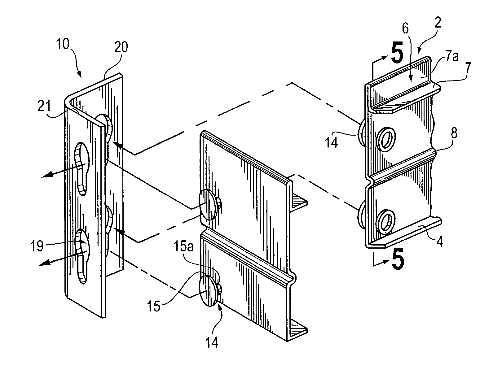
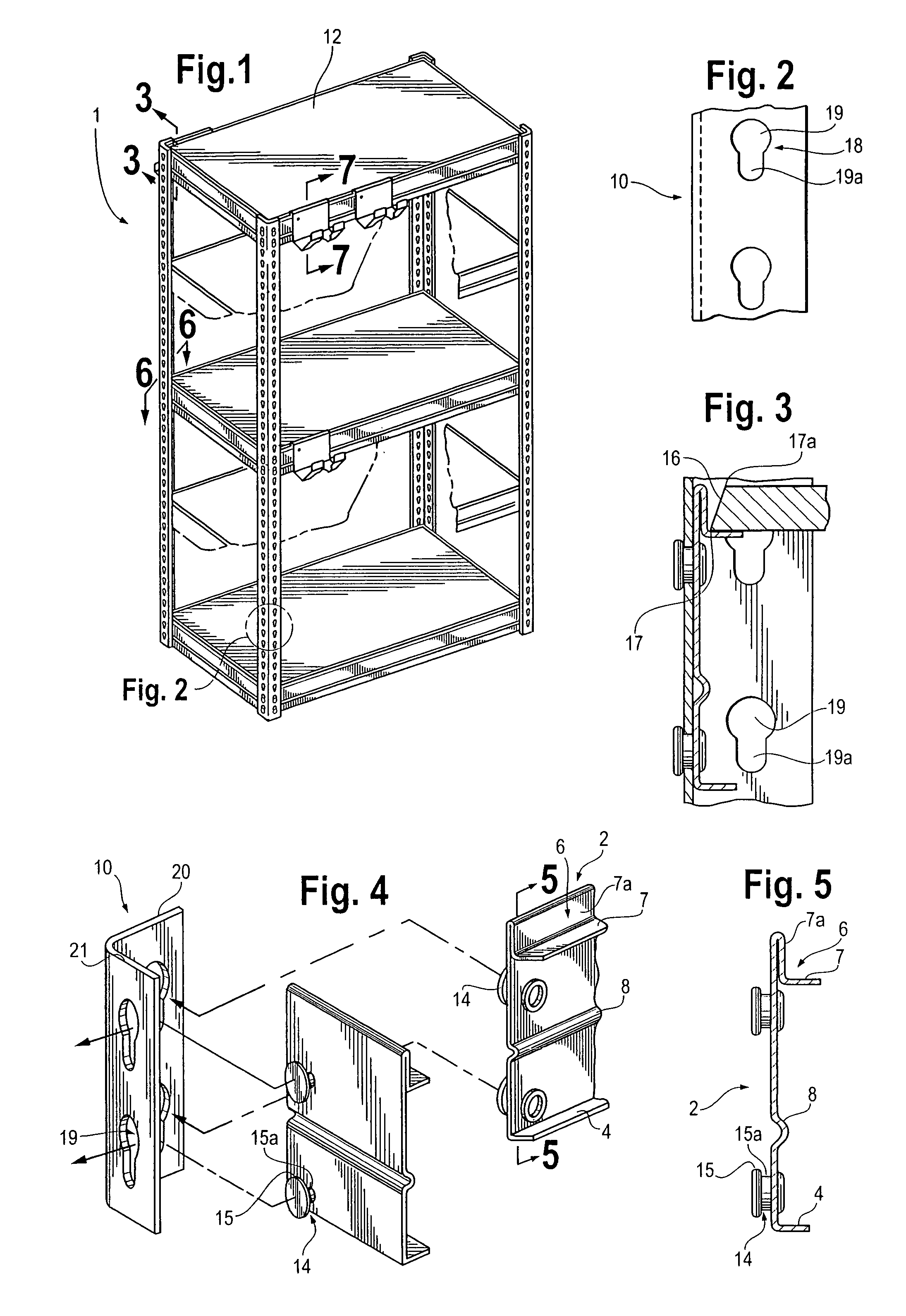
[0026]Referring to FIG. 1, the assembled shelving unit 1 is shown including four vertical posts 10. Each vertical post 10 has a pair of legs 20, 21 perpendicular to one another as shown in FIG. 4. A plurality of structural beams 2, 25, or 30 and horizontal shelving members 12 extend between the pairs of legs 20, 21 on vertical posts 10 and are attached in a manner to be described below.

[0027]The recessed structural beams 2 include a rib 8, with a recessed flange 6, and a return flange 4 as seen in FIG. 5. The rib 8, recessed flange 6, and return flange 4 terminate in a vertical edge of the recessed structural beam 2. The recessed flange 6 is chamfered at the ends of its base 7 in order to enable assembly to appear as seen in FIG. 4 once it has moved along the dashed lines to engage the legs 20, 21 of the vertical post 10.

[0028]The recessed structural beam 2 is preferably and approximately 2.5 inches in height. The recessed flange 6 is preferably and approximately 0.56 inches in heig...


PUM


Abstract

A cargo rack utilizing a structural beam in the form of three embodiments, two of the embodiments comprising a rib, one of which includes a recessed flange and a horizontal return flange, the other includes a standard angled flange and an angled return flange, the third embodiment includes a recessed flange and a horizontal return flange, structural beams used in a framework comprising a plurality of vertical posts containing key shaped apertures and a plurality of horizontal shelving members, structural beams contain nubs enabling structural beams to connect to vertical posts via key shaped apertures thereby enabling horizontal shelving members to be associated with structural beams and vertical posts, various attachments may be added to cargo rack when recessed structural beams are used via a slight clearance that is formed between the recessed edge and a slight taper on horizontal shelving member sides.

Description

BACKGROUND OF THE INVENTION[0001]This invention relates in general to a shelving unit and more particularly to the structural beams in the shelving unit. Several products are similar to this product in that they rely on beams affixed to posts to form a rigid shell that in turn supports shelf members. Examples of such prior art are illustrated in the following U.S. Pat. Nos. 5,553,549 and 5,749,481.[0002]Similar frameworks are typically provided with four vertical corner posts and a plurality of horizontal members. For example, U.S. Pat. No. 5,553,549 issued to Nilsson discloses a framework for a shelving unit comprising horizontal members, a plurality of vertical posts, and a locking attachment for connecting the horizontal members to the vertical posts. One disadvantage of this prior art design is that the horizontal support members do not provide enough load bearing capabilities. A further result of this is a poor utilization of material. The material gauge or thickness is higher ...

Claims


Application Information

Patent Timeline
Patent Type & Authority Patents(United States)
IPC IPC(8): A47B47/00A47B57/50A47B96/00A47B96/14
CPCA47B57/50A47B96/00A47B96/1441
Inventor SALTZBURG, BRUCEWOJTOWICZ, DAVIDLAMBER, JEFFERY L.ST. GERMAIN, THOMAS J.TROYNER, ANTHONY J.BIANCHIN, MITCHELL E.
Owner EDSAL MANUFACTURING COMPANY INC
Why Eureka
Try Eureka