
Filter for cleaning a fluid

a filter and fluid technology, applied in the direction of separation process, vortex flow apparatus, dispersed particle separation, etc., can solve the problem of prolonging the service life of the filter element, and achieve the effect of simple constructive measures and increased filter efficiency

Inactive Publication Date: 2011-09-06
MANN HUMMEL GMBH
View PDF26 Cites 15 Cited by
  • Summary
  • Abstract
  • Description
  • Claims
  • Application Information

AI Technical Summary

Benefits of technology

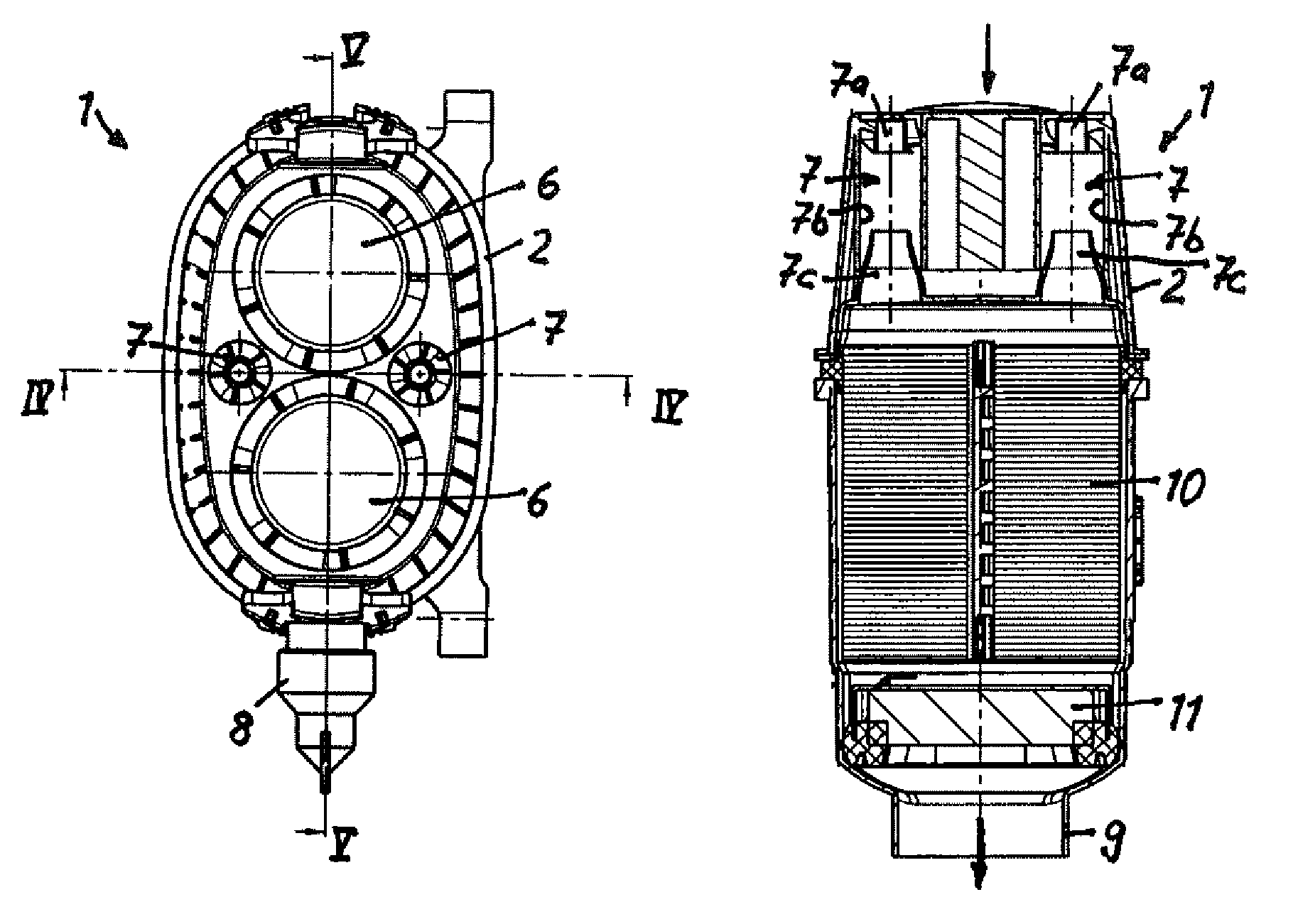
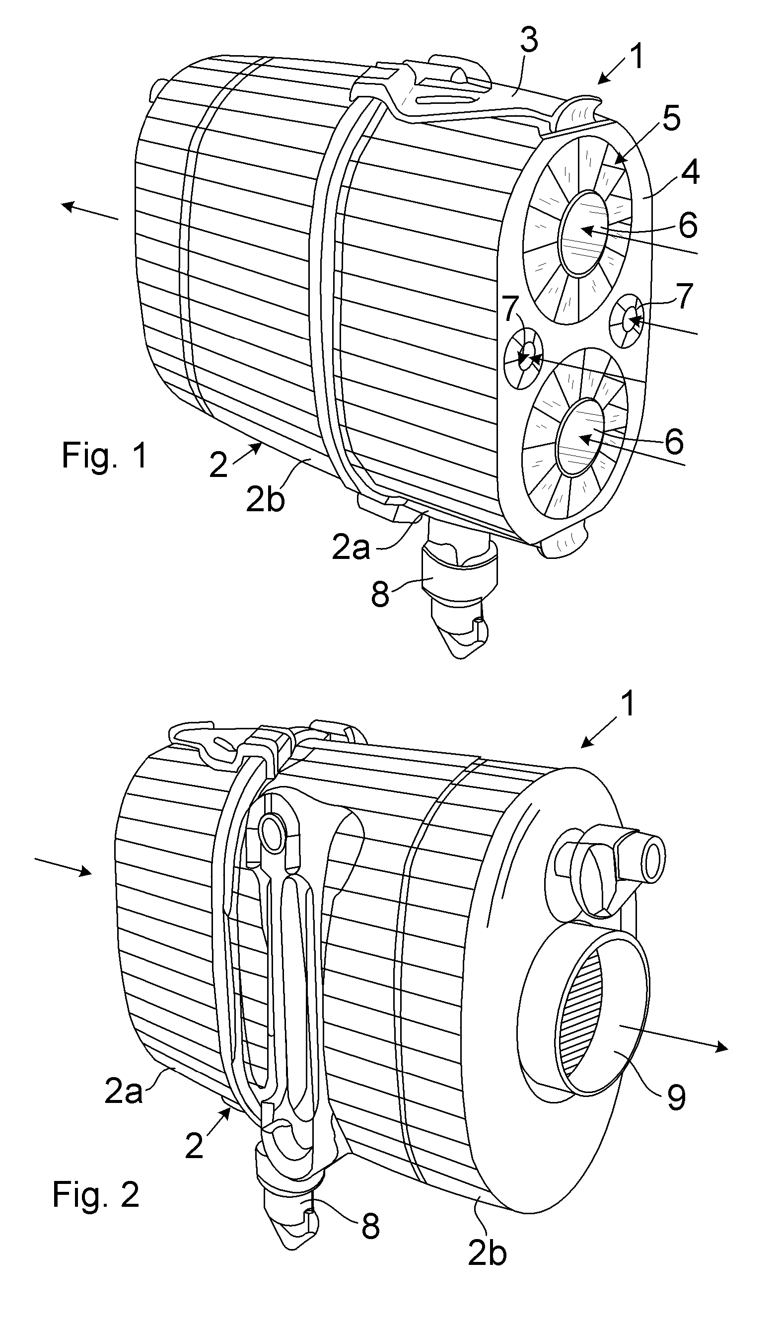
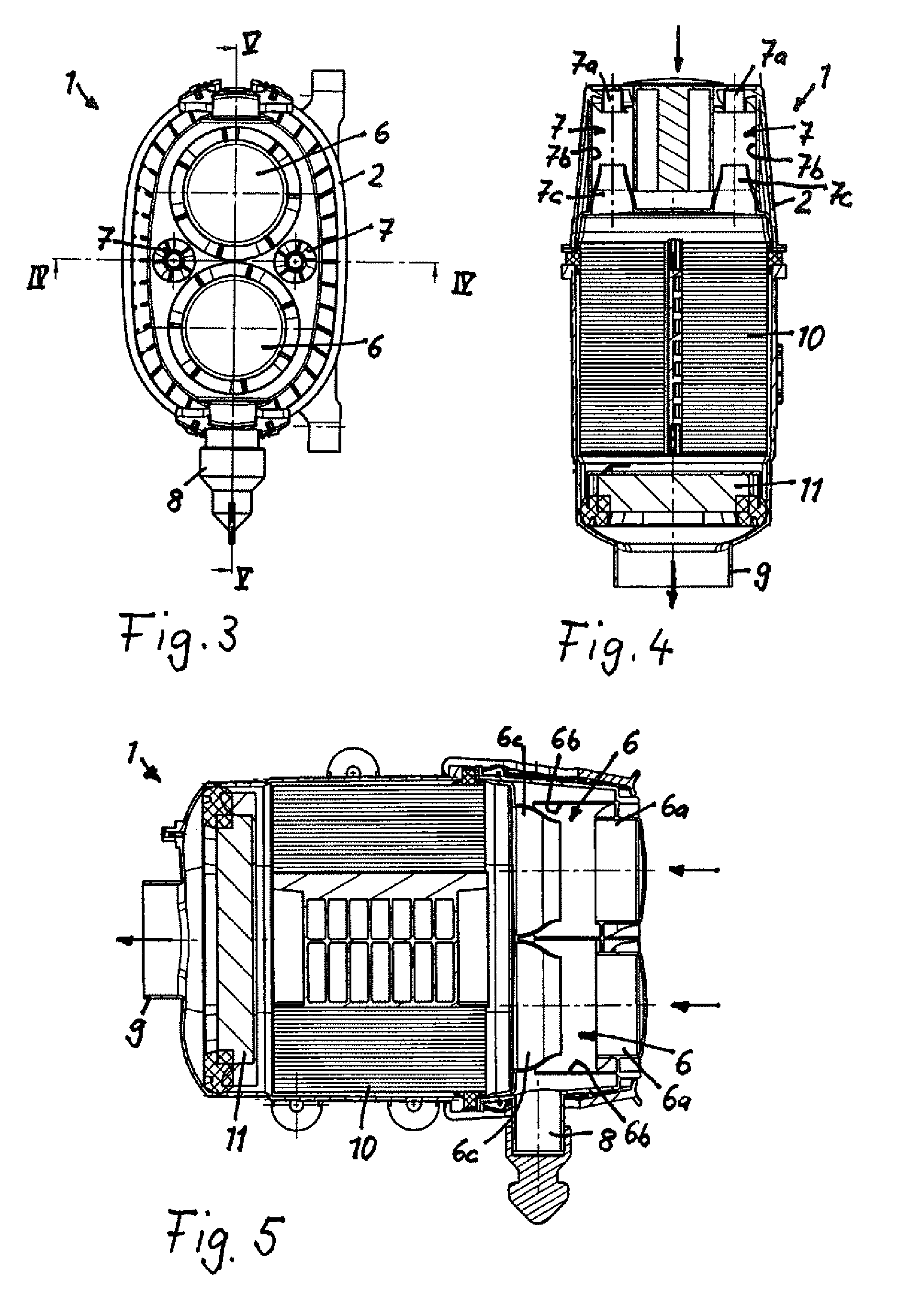
The present invention aims to increase the efficiency of a filter with a cyclone preseparator by using a simple constructive measure. This is achieved by integrating at least two cyclone cells with different diameters in the filter housing. The smaller cyclone cells provide better purification of the fluid due to their higher centrifugal forces on contaminants, while the larger cyclone cells provide better space utilization. The combination of several individual cyclones can be done in various ways, such as integrating them into the filter housing or combining them in a cyclone block that is connected to the housing. The size difference between the larger and smaller cyclone cells is desirable to maximize space utilization and increase the degree of separation. The patent text provides a detailed description of the technical effects of the invention.

Problems solved by technology

The uniform intake leads to a longer service life of the filter element.

Method used


Image

  • Filter for cleaning a fluid
  • Filter for cleaning a fluid
  • Filter for cleaning a fluid

Examples


Embodiment Construction

[0020]Before describing in detail embodiments that are in accordance with the present invention, it should be observed that the embodiments reside primarily in combinations of method steps and apparatus components related to a filter for cleaning a fluid, in particular a gaseous fluid possibly having particulate contaminants as disclosed herein. Accordingly, the apparatus components have been represented where appropriate by conventional symbols in the drawings, showing only those specific details that are pertinent to understanding the embodiments of the present invention so as not to obscure the disclosure with details that will be readily apparent to those of ordinary skill in the art having the benefit of the description herein.

[0021]In this document, relational terms such as first and second, top and bottom, and the like may be used solely to distinguish one entity or action from another entity or action without necessarily requiring or implying any actual such relationship or ...


PUM

PropertyMeasurementUnit
diameteraaaaaaaaaa
diametersaaaaaaaaaa
sizeaaaaaaaaaa

Abstract

A filter for filtering a fluid has a filter housing and a filter element arranged in the filter housing. A cyclone preseparator is arranged upstream of the filter element, wherein a fluid to be cleaned is guided through the preseparator to the filter element. The cyclone preseparator has at least two cyclone cells that have a different diameter, respectively.

Description

CROSS REFERENCE TO RELATED APPLICATIONS[0001]This application is a continuation application of international application PCT / EP2007 / 062978 having a filing date of 29 Nov. 2007, the contents of which are incorporated herein by reference in its entirety, and claims the benefit under 35 USC 119 of the filing date of foreign application DE 20 2007 004 476.3 filed in Germany on 23 Mar. 2007, the contents of which are incorporated herein by reference in its entirety.BACKGROUND OF THE INVENTION[0002]The present invention relates to a filter for cleaning a fluid, in particular a gaseous fluid, comprising a filter element arranged in a filter housing and a cyclone preseparator that is arranged upstream of the filter element and by means of which the fluid can be guided into the filter element.[0003]DE 20 2005 009 989 U1 discloses an air filter that is integrated into the intake manifold of an internal combustion engine in order to subject the combustion air to be supplied to the internal com...

Claims


Application Information

Patent Timeline
Patent Type & Authority Patents(United States)
IPC IPC(8): B01D50/00
CPCB01D45/16B01D46/525B01D50/002B04C3/04B04C9/00B04C2009/002B01D50/20
Inventor GREIF, VOLKER
Owner MANN HUMMEL GMBH
Learn More