Single saucer wing flying saucer

A flying saucer and single saucer technology, applied in the field of aircraft, can solve the problems of reducing overall weight and disadvantages, and achieve the effect of light overall weight, large room for maneuver, and simple and easy-to-manufacture overall structure

Inactive Publication Date: 2017-05-24
徐际长
View PDF3 Cites 0 Cited by
  • Summary
  • Abstract
  • Description
  • Claims
  • Application Information

AI Technical Summary

Problems solved by technology

[0003] The flying saucers designed by these applications all have double-layer saucer fins, which is relatively complicated in the design of small and micro flying saucers, especially remote-controlled unmanned flying saucers, and is also not conducive to reducing the overall weight.

Method used


Image

  • Single saucer wing flying saucer
  • Single saucer wing flying saucer
  • Single saucer wing flying saucer

Examples


Embodiment Construction

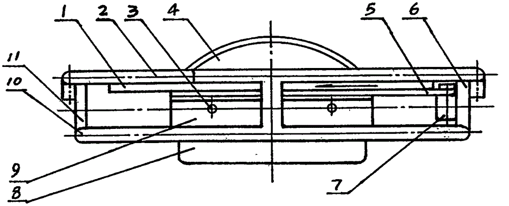
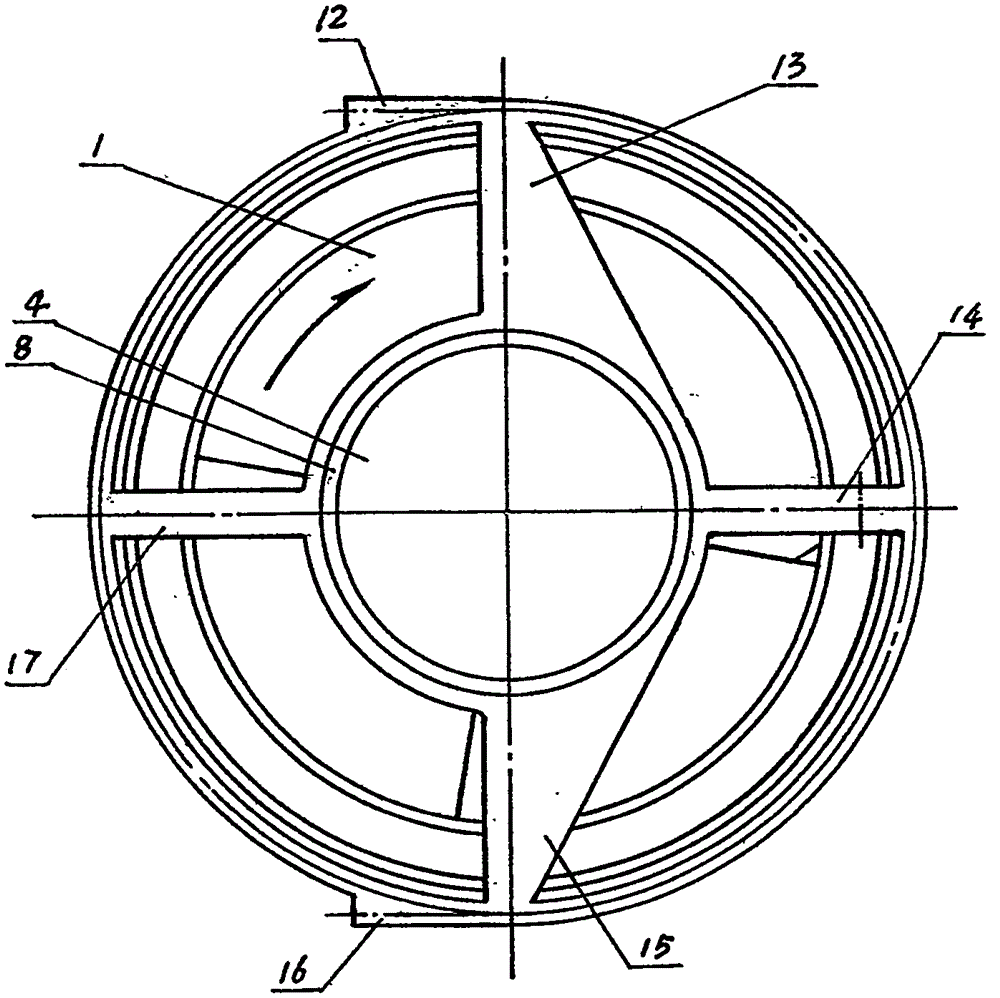
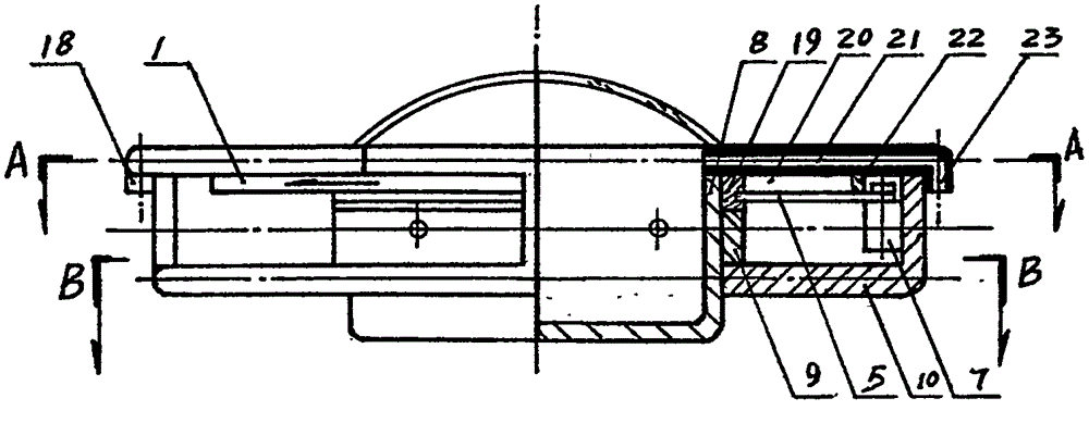
[0024] In the picture:

[0025] 1. Disc fin, 2. Upper protective ring, 3. Bolt, 4. Transparent disc hatch cover, 5. Belt, 6. Front vertical strut, 7. Motor, 8. Disc cabin body, 9. Limiting ring, 10, the lower protective ring, 11, the rear vertical strut, 12, the left air nozzle, 13, the upper left horizontal strut, 14, the front upper horizontal strut, 15, the right upper horizontal strut, 16, the right air nozzle, 17, Rear upper transverse strut, 18. Rear air nozzle, 19. Inner yoke ring, 20. Disc wing blade, 21. Air pipe, 22. Outer yoke ring, 23. Front air nozzle, 24. Interval hole, 25. Driven gear , 26, belt groove, 27, elevation angle, 28, anti-torque air nozzle, 29, left solenoid valve, 31, front solenoid valve, 32, right solenoid valve, 33, rear solenoid valve, 34, air supply mechanism.

[0026] refer to figure 1 , figure 2 , image 3 , Figure 4 and Figure 5 , Figure 6 , the front vertical strut 6 and the rear vertical strut 11 are jointly connected with the up...


PUM


Abstract

The invention discloses a single saucer wing flying saucer. The single saucer wing flying saucer is composed of a saucer cabin body, a protective cover, a power source, an operating mechanism, a thrust mechanism, and a driving mechanism; the saucer cabin body is a flat cylinder provided with a cabin; the power source is composed of batteries and an electric generator, and is arranged in the protective cover provided with a plurality of air nozzles; the saucer cabin body is movably sleeved by a single layer saucer wing; the single layer saucer wing and the lateral thrust mechanism arranged on the protective cover are used for providing the single saucer wing flying saucer with thrust; a manual control platform and a wireless control platform are arranged in the single saucer wing flying saucer; the single saucer wing flying saucer is capable of performing omnibearing flight under thrust; the operating mechanism is used for controlling the flight attitude of the single saucer wing flying saucer via a magnetic valve and the air nozzles; the volume ratio, the lift-drag ratio, the carrying capacity, and the thrust of the single saucer wing flying saucer are better than that of airplanes because of the unique shape, so that the competitiveness of the single saucer wing flying saucer is high.

Description

technical field [0001] The invention relates to an aircraft, especially a flying saucer, especially a single-winged flying saucer. Background technique [0002] I invented and applied for the patent "An Electric UFO" in July this year, application number: 201510403963.0. Later, he applied for the patent of "Flying Saucer with Rudder", application number: 201510660440.4. Later, he applied for the patent "Flying Saucer with Gas Storage Tank", application number: 201520819584.5. And the patent of "Flying Saucer with Lateral Thrust Mechanism", application number: 201510694516.5, etc. [0003] The flying saucers designed by these applications all have double-layer saucer fins, which is just relatively complicated in the design of small miniature flying saucers, especially remote-controlled unmanned flying saucers, and is not conducive to reducing the overall weight. Contents of the invention [0004] The present invention will provide a "single-winged flying saucer" with a s...

Claims


Application Information

Patent Timeline
Patent Type & Authority Applications(China)
IPC IPC(8): B64C39/06
Inventor 徐际长
Owner 徐际长
Why Eureka
Try Eureka