
Fan

A fan and blower technology, applied in the direction of liquid displacement machinery, components of pumping devices for elastic fluids, non-displacement pumps, etc., can solve the problem of no nozzles, impellers that cannot draw air normally, and no normal air flow And other issues

Inactive Publication Date: 2017-12-15
程凌军
View PDF7 Cites 0 Cited by
  • Summary
  • Abstract
  • Description
  • Claims
  • Application Information

AI Technical Summary

Problems solved by technology

The inventors conducted research on the fan and found that for the bladeless fan with this structure, when the fan assembly is running, the motor drives the impeller to rotate at a high speed, and the impeller cannot draw air normally due to idling.
At the same time, there is no normal air flow out of the nozzle
The inventor found through continuous research that this is because there is no normal air flow in the air inlet chamber, and the impeller cannot deliver air to the nozzle.

Method used


Image

  • Fan
  • Fan
  • Fan

Examples


Embodiment 2

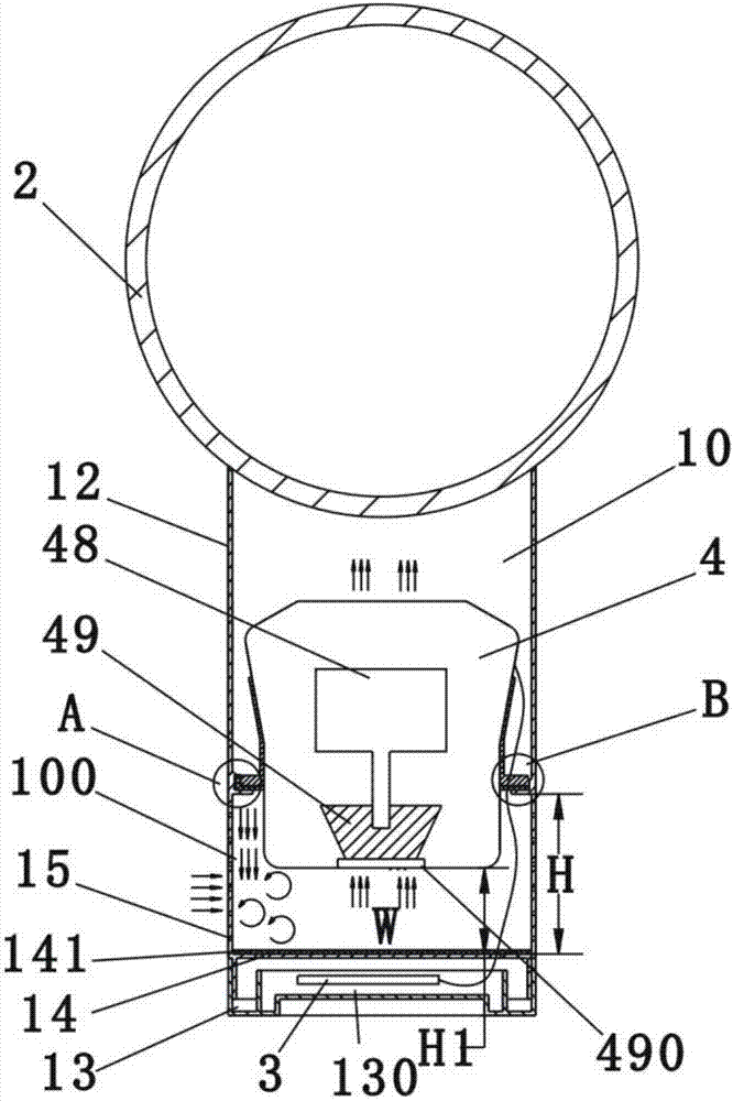
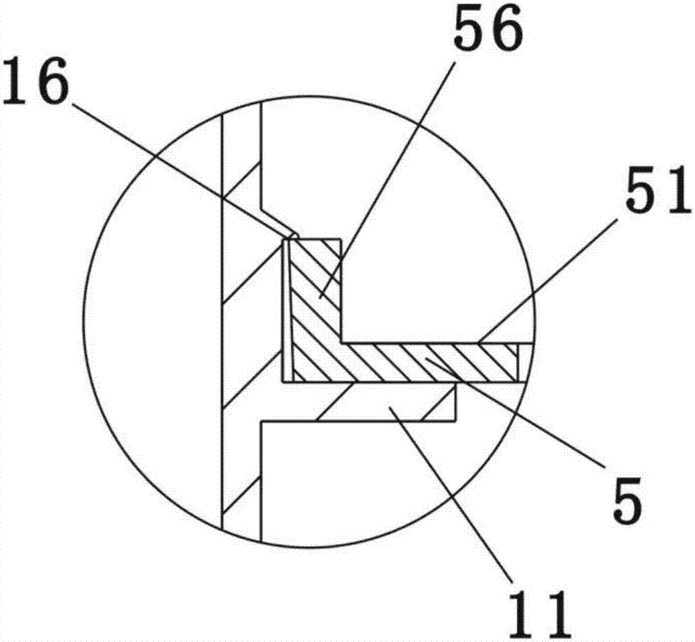
[0047] Such as Figure 9 , Figure 10 , Figure 11 Shown is a schematic structural diagram of the second embodiment of the present invention. The difference between this embodiment and Embodiment 1 is that in this embodiment, the fan assembly is only placed on the support without being fixed, and the ring-shaped holding part 41 is provided with a mounting hole 411, and the support column 8 passes through the installation hole 411 and rides on the annular support surface 51, the top of the support column 8 has an elastic limiter 81 that prevents the support column 8 from coming out of the installation hole 411, and the bottom of the support column 8 has a limit bump 82. At the same time, the support column 8 is covered with a spring 83 in a compressed state, and the upper end of the spring 83 is pressed against the lower end of the annular holding part 41, and the lower end of the spring 83 is pressed against the limit protrusion of the support column 82, wherein the shock a...


PUM


Abstract

The invention relates to a household appliance, especially a fan, which includes a base and a nozzle. A control board is arranged in the base, and a hollow cavity is installed in the base. connected fan assembly, and the upper part of the cavity is connected with the nozzle, and it is characterized in that: the inner wall of the cavity is provided with a support part for supporting the fan assembly, and the lower part of the support part forms an air inlet chamber, and the air inlet chamber A plurality of air inlet holes are arranged on the outer wall of the fan assembly, and the lower part of the fan assembly extends into the air inlet chamber through the plane where the support part is located. The height of the air intake chamber is H, and the height from the air intake opening to the bottom of the air intake chamber is H1, wherein H1 is at least greater than 1/3H. Compared with the prior art, the present invention effectively solves the problem of idling of the fan assembly.

Description

technical field [0001] The present invention relates to the technical field of household appliances, more specifically, to a fan. Background technique [0002] There is an existing patent application with the patent application number CN201710035294.5 and the invention name is "Fan". This patent application discloses a bladeless fan, wherein the motor is installed in the motor housing, and the impeller housing is connected to the lower section of the motor housing, and the annular diffuser housing is connected to the upper part of the motor housing. The sections are connected to form the whole fan assembly, and it is also disclosed in this patent application that the impeller housing is installed on the annular seat in the main part of the body to realize the installation and fixation of the whole fan assembly. [0003] For this patent application, an air inlet chamber is formed under the fan assembly, and the lower part of the fan assembly extends into the air inlet chambe...

Claims


Application Information

Patent Timeline
Patent Type & Authority Applications(China)
IPC IPC(8): F04B41/06F04D25/08F04D29/40F04D29/66
CPCF04B41/06F04D25/08F04D29/403F04D29/664F04D29/668
Inventor 程凌军
Owner 程凌军
Features
  • Generate Ideas
  • Intellectual Property
  • Life Sciences
  • Materials
  • Tech Scout
  • Unparalleled Data Quality
  • Higher Quality Content
  • 60% Fewer Hallucinations
Learn More