Efficient high-voltage generator air path

A generator and high-voltage technology, which is applied in the direction of electrical components, electromechanical devices, electric components, etc., can solve the problems of inability to install cooling fans and poor heat dissipation performance, and achieve the effects of balanced air pressure, efficient heat dissipation, and convenient installation and disassembly

Pending Publication Date: 2019-11-12
安徽德科电气科技有限公司
View PDF0 Cites 4 Cited by
  • Summary
  • Abstract
  • Description
  • Claims
  • Application Information

AI Technical Summary

Problems solved by technology

[0006] Aiming at the above-mentioned shortcomings existing in the prior art, the present invention provides a high-efficiency high-voltage generator air

Method used


Image

  • Efficient high-voltage generator air path
  • Efficient high-voltage generator air path
  • Efficient high-voltage generator air path

Examples


Example Embodiment

[0028] In order to make the purpose, technical solutions and advantages of the embodiments of the present invention more clear, the technical solutions in the embodiments of the present invention will be clearly and completely described below in conjunction with the drawings in the embodiments of the present invention. Apparently, the described embodiments are some, but not all, embodiments of the present invention. Based on the embodiments of the present invention, all other embodiments obtained by persons of ordinary skill in the art without creative efforts fall within the protection scope of the present invention.

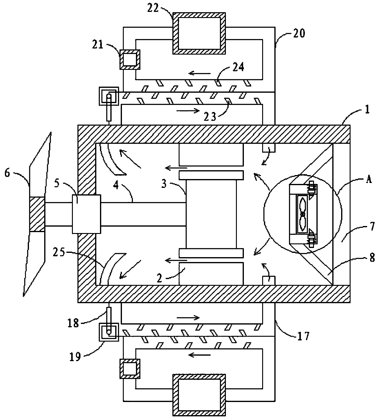
[0029] A high-efficiency high-voltage generator air circuit, such as Figure 1 to Figure 3 As shown, it includes a housing 1, a stator 2 is fixed on the inner wall of the housing 1, a rotor 3 is arranged inside the stator 2, and one end of the rotor 3 is fixed to the first rotating shaft 4, and the other end of the first rotating shaft 4 passes through the end ...


PUM


Abstract

The invention relates to a generator, in particular to an efficient high-voltage generator air path. The efficient high-voltage generator air path comprises a shell; a stator is fixed on the inner wall of the shell; a rotor is arranged inside the stator; the rotor is fixed with one end of a first rotating shaft; the other end of the first rotating shaft penetrates through the end part of the shelland is fixed with a driving wheel; the other end of the shell is provided with a dust filter net; the dust filter net is fixed with a mounting plate by a connecting rod; a placing hole is opened in the mounting plate; the rear part of the inner wall of the placing hole is fixed with a flange; an axial flow fan is placed inside the placing hole; a pulling rod passing through the side wall of the placing hole is relatively slidably connected to the mounting plate; a limiting block is fixed to the end part of the pulling rod; a mounting block is fixed to the pulling rod; and the mounting block is connected with the outer wall of the mounting plate through a spring. The technical scheme provided by the invention can effectively overcome the shortcomings of poor heat dissipation performance and the inability to install a cooling fan in the prior art.

Description

technical field [0001] The invention relates to a generator, in particular to a high-efficiency wind path of a high-voltage generator. Background technique [0002] With the development of economy and technology, the scale of the power grid continues to expand, and the market demand for energy saving, consumption reduction, and sustainable development promotes the continuous increase of the unit capacity of the generator. Otherwise, the continuous accumulation of these heat energy will cause the temperature of the internal structure of the generator to continue to rise, so that the generator will be burned. [0003] The synchronous speed of the turbogenerator can be as high as 3000r / min, and the centrifugal force on the rotor structure is large, which is limited by the material strength limit of the rotor parts such as the rotating shaft, which restricts the maximum size of the generator stator and rotor section, the circuit, the magnetic circuit, etc. Relying on the increa...

Claims


Application Information

Patent Timeline
IPC IPC(8): H02K9/18H02K9/06H02K9/26
CPCH02K9/06H02K9/18H02K9/26
Inventor 王远锋石斌
Owner 安徽德科电气科技有限公司
Why Eureka
Try Eureka