Windproof support for greenhouse

A technology of support rods and piston tubes, applied in the field of greenhouses, can solve the problems that the greenhouses are easy to be blown down, and achieve the effects of reducing the force, reducing the blocking, and preventing damage

Active Publication Date: 2018-12-04
日照市联创金属制品有限公司
View PDF4 Cites 4 Cited by
  • Summary
  • Abstract
  • Description
  • Claims
  • Application Information

AI Technical Summary

Problems solved by technology

[0003] The existing greenhouse support is generally a simple arched bamboo or steel strip. After installation, the structure is fixed. In the windy weather, because the structure is fixed and cannot be changed, the force of the strong wind is completely applied to the greenhouse. 'The way to resist strong winds, the greenhouse is very easy to be blown down

Method used


Image

  • Windproof support for greenhouse
  • Windproof support for greenhouse
  • Windproof support for greenhouse

Examples


Embodiment 1

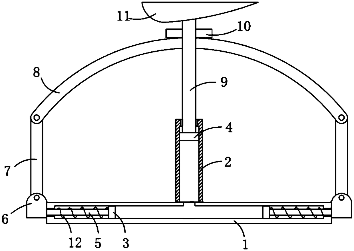
[0019] refer to Figure 1-2 , a wind-resistant greenhouse support, comprising two parallel first piston tubes 1 horizontally fixed on the ground, the two ends of the first piston tube 1 are sealed, and the ends of the two first piston tubes 1 are connected by a connecting rod ( (not shown in the figure) is connected and surrounded into a square frame shape, the middle part of the first piston tube 1 is vertically and fixedly connected with the second piston tube 2, the second piston tube 2 communicates with the first piston tube 1, and the first piston tube 1 is flexibly connected There are two first pistons 3, and the two first pistons 3 are symmetrically distributed on both sides of the second piston tube 2, the second piston tube 2 is movably connected with a second piston 4, and the second piston 4 is connected to the two first pistons. The space formed by the piston 3 is filled with hydraulic oil, the end of the first piston 3 away from the hydraulic oil is fixedly connec...

Embodiment 2

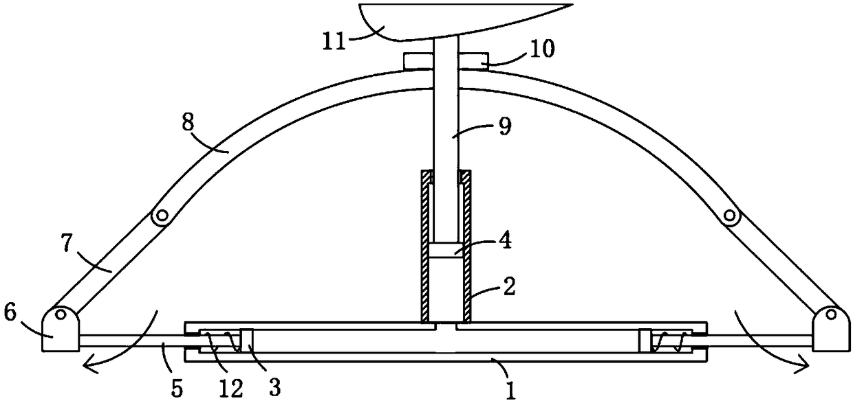
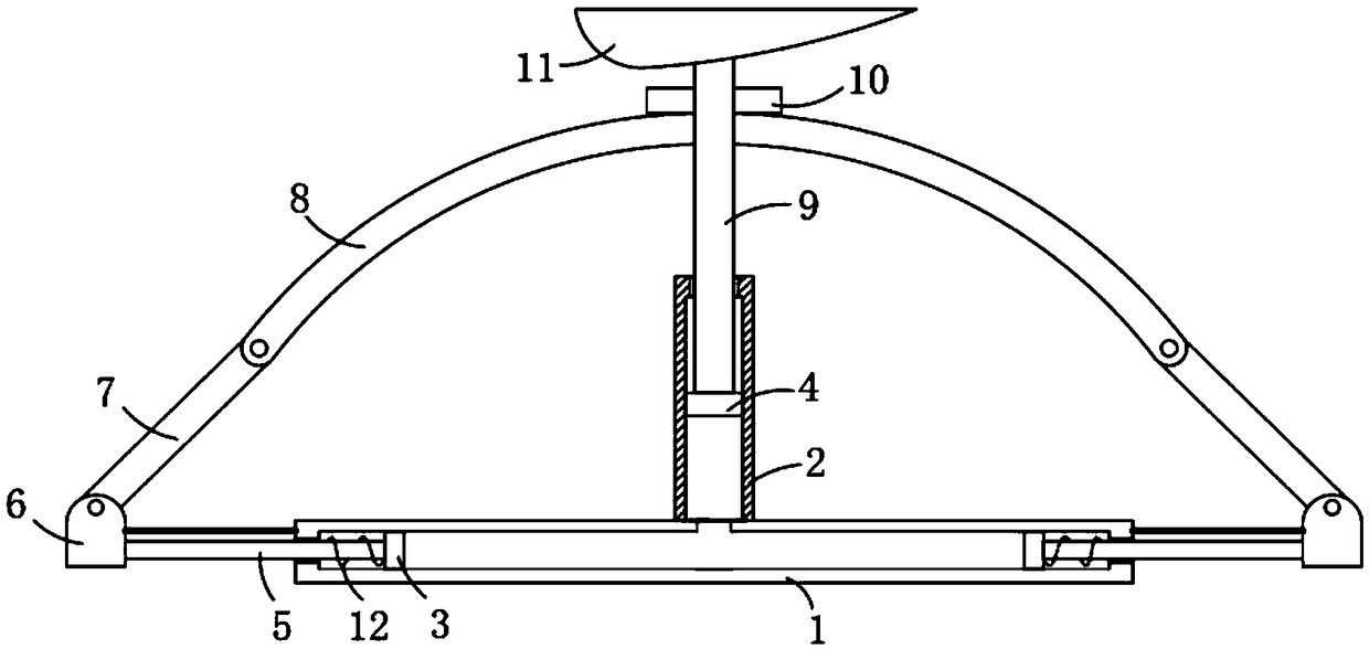
[0025] refer to Figure 3-4 , the mounting plate 6 is provided with a cavity, and a winding roller 13 is installed inside the cavity, and a sealing film 14 is wound on the winding roller, and the free end of the sealing film 14 runs through the strip hole on the side wall of the cavity and is connected with the The end face of the connecting rod and the first piston tube 1 is connected in a sealed manner.

[0026] The difference between this embodiment and Embodiment 1 is that a cavity is provided in the mounting plate 6, and a winding roller 13 is installed inside the cavity, and a sealing film 14 is wound on the winding roller, and the free end of the sealing film 14 penetrates The strip hole on the side wall of the cavity is sealed and connected with the connecting rod and the end face of the first piston tube 1. When the growth of the plants in the greenhouse requires a closed space to maintain temperature and humidity, the greenhouse cannot be closed in windy weather. Th...


PUM


Abstract

The invention discloses a windproof support for a greenhouse. The support comprises two first piston tubes which are parallel and horizontally fixed on the ground, two ends of each first piston tube are sealed, the end parts of the two first piston tubes are connected through connection rods to form a square frame shape in a surrounding manner, the middle part of each first piston tube is vertically and fixedly connected with one second piston tube, and each second piston tube communicates with one corresponding first piston tube; the interior of each first piston tube is movably connected with two first pistons, and two first pistons are symmetrically distributed on two sides of one corresponding second piston tube; and the interior of each second piston tube is movably connected with onesecond piston, the space formed by each second piston and two corresponding first pistons is filled with hydraulic oil, and one end, far away from the hydraulic oil, of each first piston is fixedly connected with one piston rod. According to the support disclosed by the invention, acting force of strong wind is utilized in the strong-wind weather, a height of the greenhouse is reduced, blockage of the wind by the greenhouse is reduced, and therefore damage of the strong wind to the greenhouse is effectively reduced.

Description

technical field [0001] The invention relates to the technical field of greenhouse frames, in particular to a wind-resistant greenhouse frame. Background technique [0002] The greenhouse was originally a special equipment for vegetable production. With the development of production, the application of greenhouses has become more and more extensive. At present, the greenhouse has been used for potted flower and cut flower cultivation; fruit tree production is used for cultivating grapes, strawberries, watermelons, melons, peaches and citrus, etc.; [0003] The existing greenhouse support is generally a simple arched bamboo or steel strip. After installation, the structure is fixed. In the windy weather, the fixed structure cannot be changed. The force of the strong wind is completely applied to the greenhouse. 'The way to resist strong winds, the greenhouse is very easy to be blown down. Contents of the invention [0004] The purpose of the present invention is to solve t...

Claims


Application Information

Patent Timeline
Patent Type & Authority Applications(China)
IPC IPC(8): A01G9/14
CPCA01G9/14Y02A40/25
Inventor 岳广琴
Owner 日照市联创金属制品有限公司
Why Eureka
Try Eureka