metal engraving device

A metal and fixed technology, applied in the field of engraving, can solve the problems of affecting the quality of engraving and increasing the difficulty of engraving work, and achieve the effect of clamping and fixing safely and stably, satisfying engraving operation, and low manufacturing cost

Inactive Publication Date: 2018-06-01
惠州市佑成五金制品有限公司
View PDF5 Cites 0 Cited by
  • Summary
  • Abstract
  • Description
  • Claims
  • Application Information

AI Technical Summary

Problems solved by technology

[0002] When engraving metal parts, it is often necessary to clamp and fix the metal parts first before engraving. The existing method usually places the metal parts directly on the ground for operation. Due to the unevenness of the ground , resulting in the position shift of the metal parts during the operation, which directly affects the engraving quality and greatly increases the difficulty of the engraving work

Method used


Image

  • metal engraving device
  • metal engraving device
  • metal engraving device

Examples


Embodiment Construction

[0019] The preferred embodiments of the present invention will be described in detail below in conjunction with the accompanying drawings, so that the advantages and features of the present invention can be more easily understood by those skilled in the art, so as to define the protection scope of the present invention more clearly.

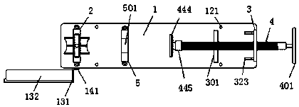
[0020] refer to Figure 1-3 As shown, a metal engraving device of the present invention includes a platen 1, a positioning clamping device 2 is provided at the top of the platen 1 close to the left side, and a vertical clamping device 2 is provided at the top right side of the platen 1 plate 3, a screw hole (not shown) is opened in the vertical plate 3, and a first screw rod 4 is fitted through the screw hole, and the right end of the first screw rod 4 is provided with a first rotating handle 401, The left end of the first screw rod 4 is provided with a push slide 444, and the top of the platen 1 is fixedly installed with a balance plate 301 betw...


PUM


Abstract

The invention discloses a metal engraving device. The metal engraving device comprises a bedplate, wherein a positioning and clamping device is arranged on the left side of the top of the bedplate, a vertical plate is arranged on the right side of the top of the bedplate, a spiral hole is formed in the vertical plate, a first spiral rod is matched in the spiral hole, a first rotating handle is arranged on the right end of the first spiral rod, a push sliding plate is arranged on the left end of the first spiral rod, a balance plate is fixedly installed on the top of the bedplate and is located between the push sliding plate and the vertical plate, the first spiral rod passes through the balance plate and is in matching connection with the balance plate, an abutting plate is arranged on the top of the bedplate and is located between the positioning and clamping device and the vertical plate, and a first putting cavity which is used for supporting a metal piece is formed in the top of the abutting plate. The metal engraving device has the advantage of simple overall structure, and a first clamping wheel is matched with a second clamping wheel, so that the metal piece can be fixedly clamped.

Description

technical field [0001] The invention relates to the technical field of engraving, in particular to a metal engraving device. Background technique [0002] When engraving metal parts, it is often necessary to clamp and fix the metal parts first before engraving. The existing method usually places the metal parts directly on the ground for operation. Due to the unevenness of the ground , resulting in the positional movement of the metal parts during the operation, which directly affects the quality of the engraving and greatly increases the difficulty of the engraving work. Contents of the invention [0003] The technical problem to be solved by the present invention is to provide a metal engraving device, which can solve the above-mentioned problems in the prior art. [0004] In order to solve the above problems, the present invention adopts the following technical solutions: [0005] A metal engraving device according to the present invention comprises a platen, a positi...

Claims


Application Information

Patent Timeline
Patent Type & Authority Patents(China)
IPC IPC(8): B44B1/00B44B1/06B44B3/00B44B3/06
CPCB44B1/00B44B1/06B44B3/00B44B3/065
Inventor 聂值清
Owner 惠州市佑成五金制品有限公司
Why Eureka
Try Eureka