
A liquid crystal display polishing and grinding device

A liquid crystal display and processing device technology, which is applied in the field of polishing, can solve the problems of reducing the polishing effect of the display surface, reducing the polishing effect, and increasing the cost budget, so as to reduce the risk of flying out or breaking the screen, enhance the polishing effect, and use rate-boosting effect

Active Publication Date: 2020-06-16
深圳市新世纪拓佳光电技术有限公司
View PDF6 Cites 0 Cited by
  • Summary
  • Abstract
  • Description
  • Claims
  • Application Information

AI Technical Summary

Problems solved by technology

[0002] The liquid crystal display needs to be polished before leaving the factory. Generally, the equipment of this process usually adopts horizontal and vertical axial polishing. This polishing method has a small polishing area, which is easy to reduce the polishing effect of the display surface, and the clamping during polishing Very unstable, easy to break and fly out of the product, which increases the cost budget. It is also very inconvenient to install the screen, and it cannot be installed at the appropriate height and direction for the operator. In addition, when polishing the screen, the general equipment sprays polishing liquid and The coolant cannot fully contact the screen, which will reduce the polishing effect, and the waste liquid after use cannot be used reasonably

Method used


Image

  • A liquid crystal display polishing and grinding device
  • A liquid crystal display polishing and grinding device
  • A liquid crystal display polishing and grinding device

Examples


Embodiment Construction

[0019] Combine below Figure 1-5 The present invention is described in detail, and for convenience of description, the orientations mentioned below are now stipulated as follows: figure 1 The up, down, left, right, front and back directions of the projection relationship itself are the same.

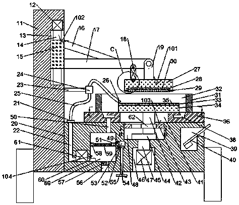
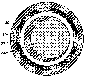
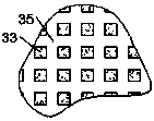
[0020] refer to Figure 1-5 According to an embodiment of the present invention, a liquid crystal display polishing and grinding device includes a support plate 11 and a base 20, the right side of the support plate 11 is fixedly connected to the left side of the base 20, and the support The plate 11 is provided with a sliding chamber 13 with an opening to the right. The left wall of the sliding chamber 13 slides up and down and is provided with a slider 15. The right side of the slider 15 is fixed with a cross bar 17, and the cross bar 17 The right side of the hinge is provided with a connecting rod 19, the bottom surface of the connecting rod 19 is fixed with a clamping plate 27, and ...


PUM


Abstract

The invention discloses a polishing and grinding device for a liquid crystal display screen. The polishing and grinding device comprises a supporting plate and a base, the right side of the supportingplate is fixedly connected with the left side of the base, a sliding cavity with an opening facing rightwards is formed in the supporting plate, a slider capable of sliding up and down is arranged onthe left wall of the sliding cavity, and the right side of the slider is fixedly provided with a transverse rod. A connecting rod is hinged to the right side of the transverse rod, the bottom face ofthe connecting rod is fixedly provided with a clamping plate, a clamping mechanism capable of sucking and clamping the display screen is arranged in the clamping plate, and a control mechanism capable of controlling the slider to drive the clamping plate to move up and down and controlling the connecting rod to rotate is arranged in the sliding cavity. By means of the polishing and grinding device, the polishing and grinding efficiency of the liquid crystal screen can be improved, the polishing effect of the surface of the liquid crystal display screen can be further enhanced, and a polishingcooling mixed solution can be recycled and reused.

Description

technical field [0001] The invention relates to the technical field of polishing, in particular to a liquid crystal display polishing and grinding device. Background technique [0002] The liquid crystal display needs to be polished before leaving the factory. Generally, the equipment of this process usually adopts horizontal and vertical axial polishing. This polishing method has a small polishing area, which is easy to reduce the polishing effect of the display surface, and the clamping during polishing Very unstable, easy to break and fly out of the product, which increases the cost budget. It is also very inconvenient to install the screen, and it cannot be installed at the appropriate height and direction for the operator. In addition, when polishing the screen, the general equipment sprays polishing liquid and The cooling liquid cannot fully contact the screen, which will reduce the polishing effect, and the waste liquid after use cannot be used reasonably. Contents ...

Claims


Application Information

Patent Timeline
Patent Type & Authority Patents(China)
IPC IPC(8): G02F1/13
CPCG02F1/1303
Inventor 樊宽江
Owner 深圳市新世纪拓佳光电技术有限公司
Learn More