
Drum washing machine and washing barrel assembly used in the same

A technology for drum washing machines and washing tubs, which can be applied to other washing machines, applications, washing devices, etc., and can solve the problems of increased power consumption costs, affecting spraying effects, and low spraying efficiency, so as to reduce power consumption costs and improve spraying effects Good, high spraying efficiency

Active Publication Date: 2017-12-22
WUXI LITTLE SWAN ELECTRIC CO LTD
View PDF12 Cites 2 Cited by
  • Summary
  • Abstract
  • Description
  • Claims
  • Application Information

AI Technical Summary

Problems solved by technology

[0002] The drum washing machine lifts and beats the clothes through the rotation of the washing tub for washing. The outside of the washing tub is usually equipped with a water circulation spray device, and the water in the washing tub is pumped out of the washing tub through a circulation pipe by using external force such as a circulation pump, and then The spraying device returns to the washing tub. In order to achieve this process, the circulating pump needs to work continuously, resulting in increased power consumption costs
[0003] For this reason, in the related art, a technical scheme of installing a water intake device on the washing bucket is proposed, but the water intake device uses an open flow channel to guide the water between the washing bucket and the water tank into the washing bucket, that is, the periphery of the flow channel Open, so that water is easy to spill from the opening around the flow channel during the rotation of the water intake device, resulting in a small amount of spray water and insufficient spray pressure, which affects the spray effect and low spray efficiency

Method used


Image

  • Drum washing machine and washing barrel assembly used in the same
  • Drum washing machine and washing barrel assembly used in the same
  • Drum washing machine and washing barrel assembly used in the same

Examples


Embodiment Construction

[0037] The embodiments of the present invention will be described in detail below. Examples of the embodiments are shown in the accompanying drawings, wherein the same or similar reference numerals indicate the same or similar elements or elements with the same or similar functions. The embodiments described below with reference to the drawings are exemplary, and are only used to explain the present invention, but should not be understood as limiting the present invention.

[0038] In the description of the present invention, it should be understood that the terms "center", "upper", "lower", "inner", "outer", "axial", "radial", "circumferential", etc. indicate The orientation or positional relationship is based on the orientation or positional relationship shown in the drawings, which is only for the convenience of describing the present invention and simplifying the description, and does not indicate or imply that the device or element referred to must have a specific orientation...


PUM


Abstract

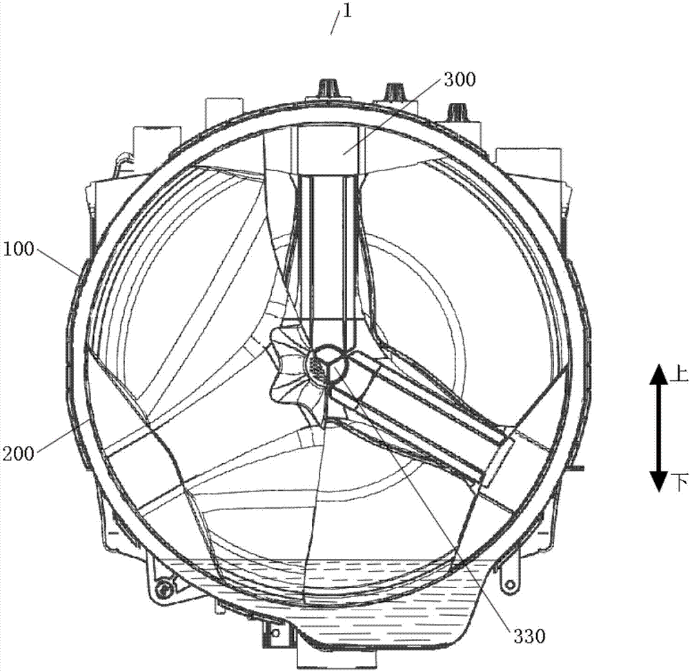
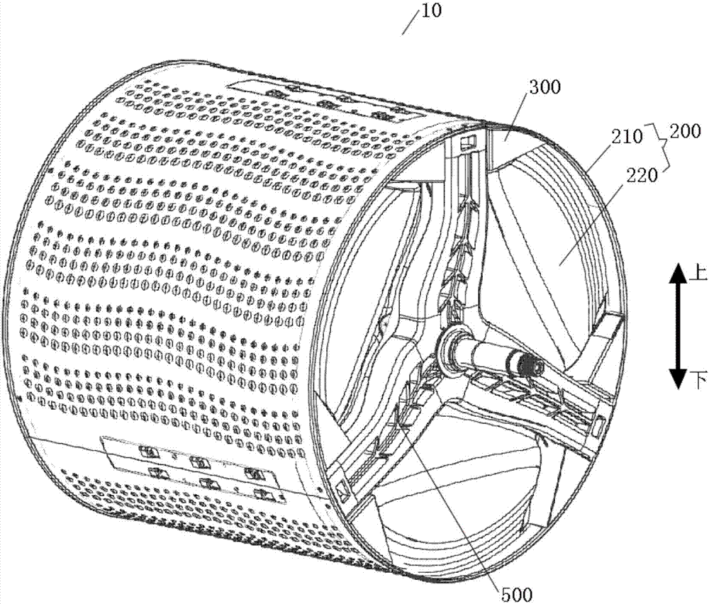
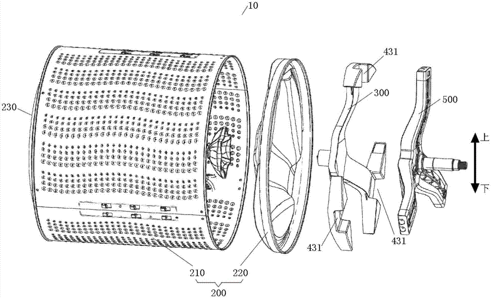
The invention discloses a drum washing machine and a washing barrel assembly used in the same. The drum washing machine comprises a water barrel, a washing barrel, a water taking device and one-way connecting devices, wherein the washing barrel is rotationally arranged in the water barrel; the water taking device rotates along with the washing barrel and is provided with water taking openings, a flow channel and a spraying opening, the spraying opening is communicated with the inner space of the washing barrel, and the flow channel with the periphery closed is communicated with the water taking openings and the spraying opening; the one-way connecting devices are arranged on the water taking openings and achieve one-way connection from the outer sides of the water taking openings to the inner sides of the water taking openings; when the water taking device rotates along with the washing barrel, liquid in the water barrel is scooped by the water taking openings and flows into the washing barrel from the spraying opening along the flow channel under the action of gravity. The drum washing machine has the advantages of being low in power consumption cost, good in spraying effect, high in spraying efficiency and the like.

Description

Technical field [0001] The present invention relates to the technical field of electrical appliance manufacturing, in particular to a drum washing machine and a washing tub assembly for the drum washing machine. Background technique [0002] The drum washing machine uses the rotation of the drum to lift and beat the clothes to wash. The outside of the drum is usually equipped with a water circulation spray device. The water in the drum is pumped out of the drum through the circulation pipe by external force such as a circulating pump. The spray device returns to the washing tub. In order to realize this process, the circulating pump needs to continue to work, resulting in an increase in power consumption costs. [0003] For this reason, the related art proposes a technical solution of installing a water intake device on the washing tub, but the water intake device uses an open flow channel to guide the water between the washing tub and the water tub into the washing tub, that is, t...

Claims


Application Information

Patent Timeline
IPC IPC(8): D06F39/08D06F37/04
CPCD06F37/04D06F39/083D06F39/088
Inventor 唐启庆金炅学熊士昌
Owner WUXI LITTLE SWAN ELECTRIC CO LTD
Learn More