
Desk-type electric iron with lock catch fixing device

The technology of fixing device and electric iron, which is applied in the direction of hand iron, washing device, textile and paper making, etc., can solve the problems of falling damage of iron, uncertainty of iron, injury of user, etc., and achieve the effect of ensuring safe state and simple operation.

Active Publication Date: 2017-12-26
NINGBO HEIGER ELECTRICAL APPLIANCES
View PDF9 Cites 5 Cited by
  • Summary
  • Abstract
  • Description
  • Claims
  • Application Information

AI Technical Summary

Problems solved by technology

Common desktop electric irons on the market are generally composed of two parts: the table body (steam generator) and the iron (working machine). The table body and the iron are connected by a composite pipeline that combines steam hoses and electrical circuits. When moving the whole machine, the iron is usually placed on the heat insulation board of the table body. Due to the instability of the iron placement and the composite pipeline at the end of the iron has an uncertain stress on the iron, the iron often turns over. In the event of falling or slipping, it may cause the iron itself to fall and be damaged, or cause the user to be injured or scalded (especially when there is still residual heat on the soleplate of the iron just after ironing)

Method used


Image

  • Desk-type electric iron with lock catch fixing device
  • Desk-type electric iron with lock catch fixing device
  • Desk-type electric iron with lock catch fixing device

Examples


Embodiment Construction

[0031] In order to have a further understanding and understanding of the structural features of the present invention and the achieved effects, the preferred embodiments and accompanying drawings will be used for a detailed description, as follows:

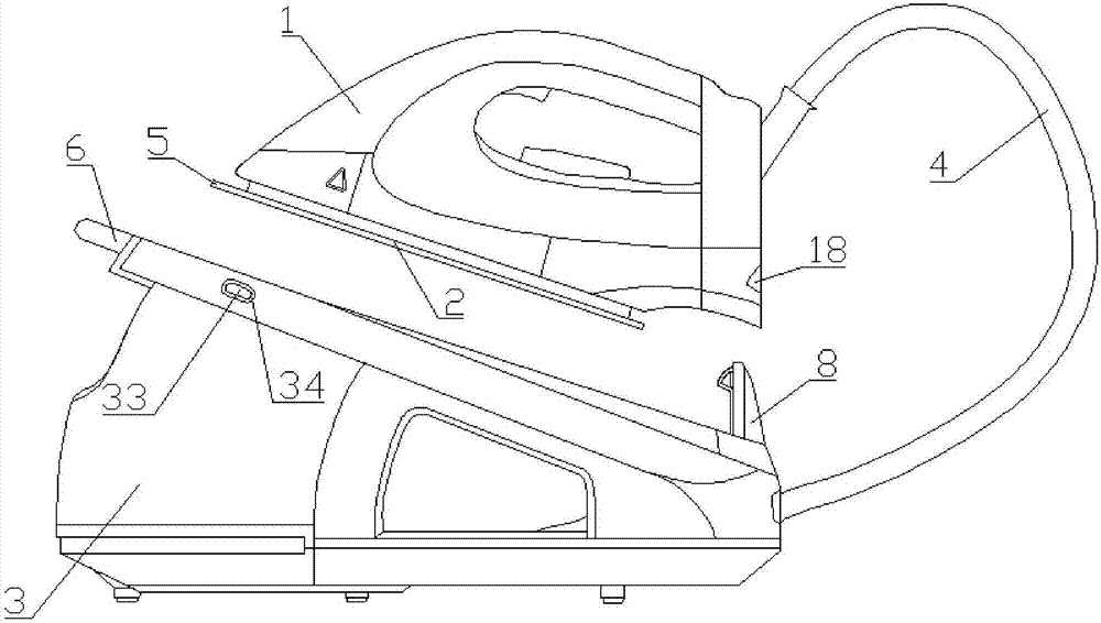
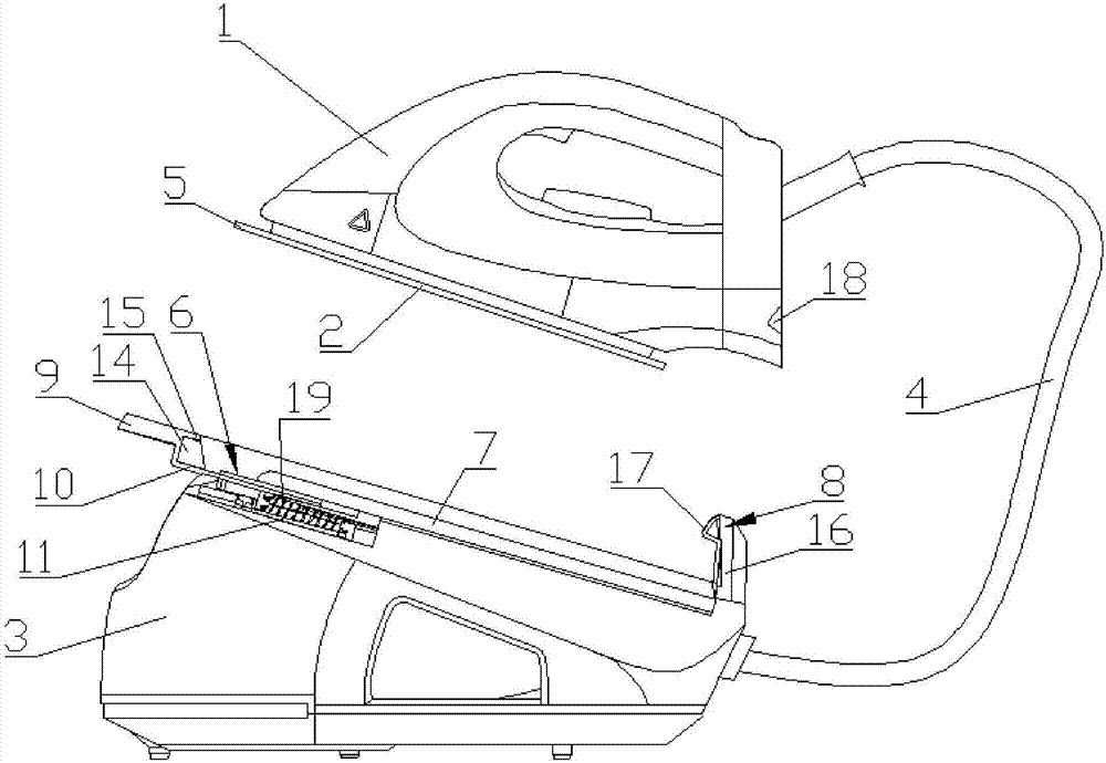
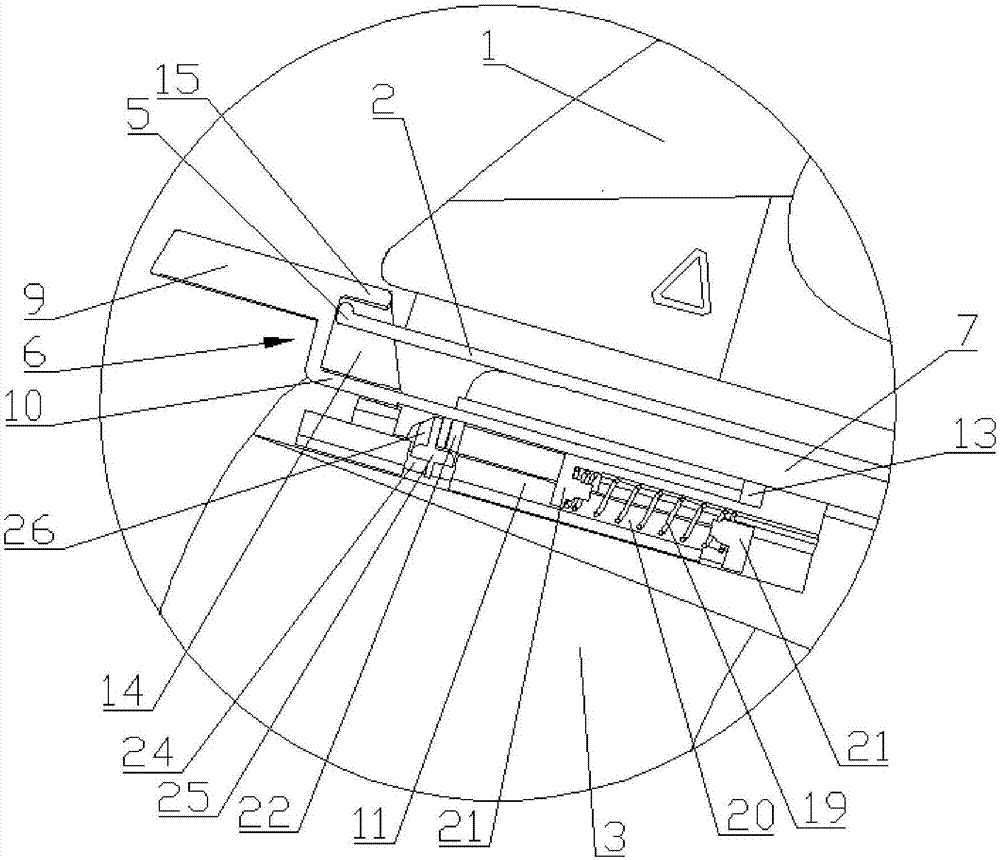
[0032] The invention discloses a table-top electric iron with a lock fixing device. figure 1 It is a schematic diagram of the external structure of the desktop electric iron in the present invention, figure 2 It is a schematic cross-sectional view of the locking and fixing device in the present invention. Depend on figure 1 and figure 2 As shown, the table body 3 including the iron and the built-in lock fixing device for placing the iron, the rear end of the table body 3 and the rear end of the iron are connected to each other by a composite pipeline 4; the composite pipeline 4 has a built-in steam hose (not shown) output) and electrical circuit (not shown), the composite pipeline 4 iron includes iron body 1 and iron soleplat...


PUM

PropertyMeasurementUnit
Angleaaaaaaaaaa

Abstract

The invention discloses a desk-type electric iron with a lock catch fixing device. The electric iron comprises an iron body, an iron baseboard and a desk body which is internally provided with the lock catch fixing device; a protrusion lip part is arranged at the front end of the iron baseboard; the lock catch fixing device comprises a lock catch mechanism, a desk body heat insulation board and an iron buckling mechanism; the lock catch mechanism comprises a lock catch push board, a lock catch push disc and a lock catch bracket; the lock catch push board is connected with the front end of the top of the lock catch push disc, the lock catch push disc is arranged above the lock catch bracket, screw hole fixing supports are arranged at the periphery of the lock catch bracket, slide grooves are formed in the left side and the right side of the lock catch bracket, and the lock latch push disc slides front and back along the slide grooves; the lock latch push disc is provided with a limiting protrusion board located above the protrusion lip part; the iron buckling mechanism comprises a heelpiece baffle arranged at the rear end of the desk body, the heelpiece baffle is provided with a fixed clamping block, and a fixed groove is formed in the rear portion of the iron. The iron can be effectively fixed to the desk body, the effect of locking and placing the iron and unlocking and taking out the iron is good, and the safety effect is effectively improved.

Description

technical field [0001] The invention relates to the field of electric iron manufacturing, in particular to a desktop electric iron with a lock fixing device. Background technique [0002] With the continuous development of people's lives, electric irons have gradually become one of the more common household appliances. Common desktop electric irons on the market are generally composed of two parts: the table body (steam generator) and the iron (working machine). The table body and the iron are connected by a composite pipeline that combines steam hoses and electrical circuits. When moving the whole machine, the iron is usually placed on the heat insulation board of the table body. Due to the instability of the iron placement and the composite pipeline at the end of the iron has an uncertain stress on the iron, the iron often turns over. In the event of falling or slipping, it may cause the iron itself to fall and be damaged, or cause the user to be injured or scalded (espec...

Claims


Application Information

Patent Timeline
IPC IPC(8): D06F75/40
CPCD06F75/40
Inventor 姚能宜
Owner NINGBO HEIGER ELECTRICAL APPLIANCES
Learn More