Automated peritoneal dialysis machine

A technology of peritoneal dialysis machine and dialysate, applied in the medical field, can solve problems such as loss of exchange, contamination of patients, infection, etc., to achieve the effect of ensuring a safe state and improving efficiency

Active Publication Date: 2017-02-22
SHENZHEN INST OF ADVANCED TECH
View PDF21 Cites 2 Cited by
  • Summary
  • Abstract
  • Description
  • Claims
  • Application Information

AI Technical Summary

Problems solved by technology

[0002] At present, hemodialysis and peritoneal dialysis are used in the treatment of uremia. At present, more than 99% of the peritoneal dialysis treatments performed clinically in my country use manual operations. Manual operations are easy to cause pollution and cause patients to be infected. Peritoneal infection is the most common cause of peritoneal dialysis. A common and serious consequence is that peritoneal sclerosis loses the function of exchange. Automated peritoneal dialysis uses a cycler (peritoneal dialysis machine) to exchange fluid at night, and keeps the dialysate in the abdomen during the day, which is called automated peritoneum. Currently, imported The fully automatic peritoneal dialysis machine, because its liquid injection method is to use air pressure to make the dialysate enter the peritoneal cavity, and use negative pressure to suck out the elicited liquid, which will easily cause the peritoneal dialysis tube to be blocked by the adhesion of its inner membrane, and the waste liquid will not be drawn out completely, resulting in stasis Medical malpractice due to high intra-abdominal pressure
At the same time, since the automatic peritoneal dialysis is treated at home and is started before going to bed until dawn, the current equipment has not monitored the bleeding or infection during the treatment, which may lead to the possibility of medical accidents

Method used


Image

  • Automated peritoneal dialysis machine
  • Automated peritoneal dialysis machine

Examples


Embodiment Construction

[0008] Embodiments of the present invention are described in detail below, examples of which are shown in the drawings, wherein the same or similar reference numerals designate the same or similar elements or elements having the same or similar functions throughout. The embodiments described below by referring to the figures are exemplary only for explaining the present invention and should not be construed as limiting the present invention.

[0009] In the description of the present invention, the orientation or positional relationship indicated by the terms "inner", "outer", "longitudinal", "transverse", "upper", "lower", "top", "bottom" etc. are based on the drawings The orientations or positional relationships shown are only for the convenience of describing the invention and do not require the invention to be constructed and operated in a specific orientation, and thus should not be construed as limitations on the invention.

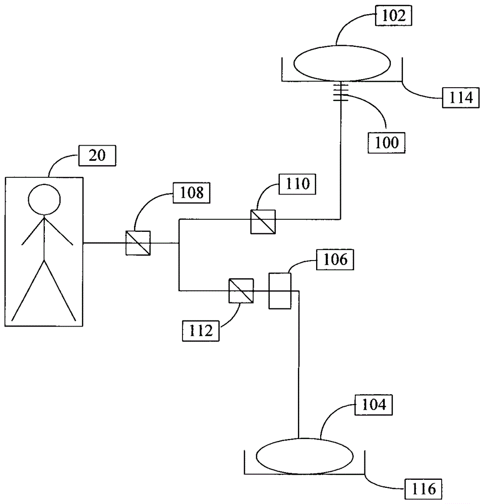
[0010] see figure 1 , figure 1 Shown is a s...


PUM


Abstract

An automatic peritoneal dialysis machine comprises a dialyzate bag, a heater, a waste liquid bag, a safety detector, a first valve, a second valve and a third valve. Dialyzate in the dialyzate bag is heated to the set temperature through the heater, the first valve and the second valve are opened, the third valve is closed, the heated dialyzate flows into an abdominal cavity of a patient, when the pouring amount of the dialyzate reaches the preset value, the first valve is closed, the dialyzate stays in the abdominal cavity of the patient to conduct dialysis and diffusion, when the time that the dialyzate stays in the abdominal cavity of the patient reaches the preset time, the first valve and the third valve are opened, the dialyzate exchanged in the abdominal cavity is led out of the waste liquid bag, and after the amount of the led-out dialyzate is consistent with the amount of the poured dialyzate, the first valve and the third valve are closed. The safety detector leads out the dialyzate exchanged in the abdominal cavity and conducts blood leakage detection on the dialyzate exchanged in the abdominal cavity. The machine effectively ensures the safety state of the patient in the dialysis process, and improves the dialysis efficiency.

Description

technical field [0001] The invention relates to medical technology, in particular to an automatic peritoneal dialysis machine. Background technique [0002] At present, hemodialysis and peritoneal dialysis are used in the treatment of uremia. At present, more than 99% of the peritoneal dialysis treatments performed clinically in my country use manual operations. Manual operations are easy to cause pollution and cause patients to be infected. Peritoneal infection is the most common cause of peritoneal dialysis. A common and serious consequence is that peritoneal sclerosis loses the function of exchange. Automated peritoneal dialysis uses a cycler (peritoneal dialysis machine) to exchange fluid at night, and keeps the dialysate in the abdomen during the day, which is called automated peritoneum. Currently, imported The fully automatic peritoneal dialysis machine, because its liquid injection method is to use air pressure to make the dialysate enter the peritoneal cavity, and use...

Claims


Application Information

Patent Timeline
Patent Type & Authority Patents(China)
IPC IPC(8): A61M1/28
CPCA61M1/28A61M2205/15A61M2205/18A61M2205/3306
Inventor 唐勋宏
Owner SHENZHEN INST OF ADVANCED TECH
Why Eureka
Try Eureka