External-circulating cooling mechanism for hydraulic turbine generator thrust bearing
An external circulation cooling and hydro-generator technology, applied in bearing cooling, hydroelectric power generation, bearing components, etc., can solve the problem of the cooling effect of thrust bearing and the difficulty of taking into account the space for installation and maintenance, shorten the installation and maintenance period, and achieve good economic benefits. , the effect of improving efficiency
- Summary
- Abstract
- Description
- Claims
- Application Information
AI Technical Summary
Problems solved by technology
Method used
Image
Examples
Embodiment 1
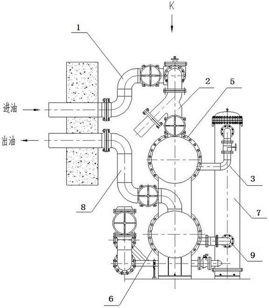
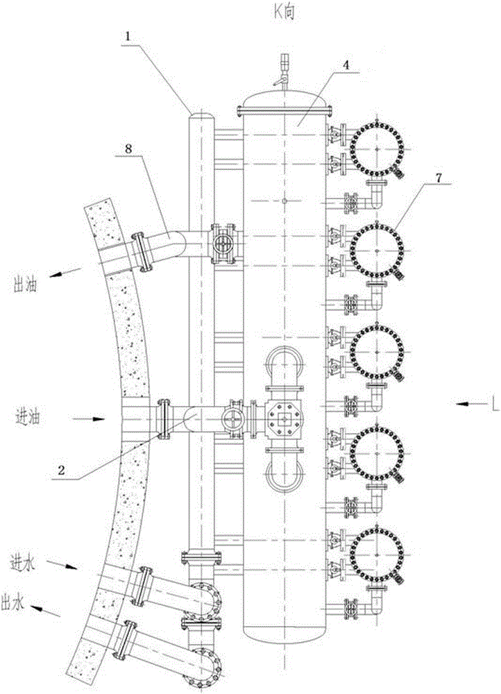
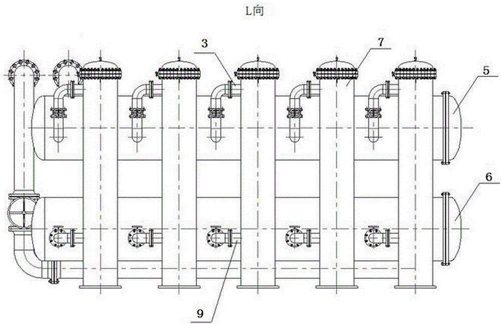
[0025] As a preferred embodiment of the present invention, with reference to the attached figure 1 , this example discloses:
[0026] An external circulation cooling structure for a thrust bearing of a hydroelectric generator, comprising an external circulation cooling pipeline 1 and a cooler 7 , and an oil tank 4 is arranged on the external circulation cooling pipeline 1 . By setting the oil tank 4 on the thrust bearing outer circulation cooling pipeline 1, the lubricating oil in the thrust bearing outer circulation can be increased, so that the volume of the thrust oil tank can be reduced under the premise of ensuring the thrust bearing cooling effect, thereby increasing the installation of thrust bearings and other components The maintenance space shortens the installation and maintenance cycle; the reduction of the lubricating oil in the thrust oil tank can reduce the stirring loss of the thrust bearing, improve the efficiency of the generator, and achieve better economic ...
Embodiment 2
[0028] As another preferred embodiment of the present invention, this embodiment discloses:
[0029] An outer circulation cooling structure for a thrust bearing of a hydroelectric generator, characterized in that it includes an outer circulation cooling pipeline 1 and a cooler 7, and an oil tank 4 is arranged on the outer circulation cooling pipeline 1; the oil tank 4 is arranged outside Between the main oil inlet pipe 2 of the circulating cooling pipeline 1 and the oil inlet branch pipe 3; one end of the oil inlet branch pipe 3 is connected to the oil tank 4, and the other end is connected to the cooler 7. By setting the oil tank 4 between the oil inlet main pipe 2 and the oil inlet branch pipe 3 of the thrust bearing outer circulation cooling pipeline 1, the lubricating oil of the thrust bearing outer circulation can be increased, so that the thrust can be reduced under the premise of ensuring the cooling effect of the thrust bearing The volume of the oil tank increases the ...
Embodiment 3
[0031] As another preferred embodiment of the present invention, this embodiment discloses:
[0032] An outer circulation cooling structure for a thrust bearing of a hydroelectric generator, characterized in that it includes an outer circulation cooling pipeline 1 and a cooler 7, and an oil tank 4 is arranged on the outer circulation cooling pipeline 1; the oil tank 4 is arranged outside Between the main oil outlet pipe 8 and the oil outlet branch pipe 9 of the circulating cooling pipeline 1; one end of the oil outlet branch pipe 9 is connected to the oil tank 4, and the other end is connected to the cooler 7. By setting the oil tank 4 between the oil outlet main pipe 8 and the oil outlet branch pipe 9 of the thrust bearing outer circulation cooling pipeline 1, the lubricating oil of the thrust bearing outer circulation can be increased, so that the thrust can be reduced under the premise of ensuring the cooling effect of the thrust bearing The volume of the oil tank increases...
PUM
 Abstract
Description
Claims
Application Information
 - R&D
- Intellectual Property
- Life Sciences
- Materials
- Tech Scout
- Unparalleled Data Quality
- Higher Quality Content
- 60% Fewer Hallucinations
Browse by: Latest US Patents, China's latest patents, Technical Efficacy Thesaurus, Application Domain, Technology Topic, Popular Technical Reports.
© 2025 PatSnap. All rights reserved.Legal|Privacy policy|Modern Slavery Act Transparency Statement|Sitemap|About US| Contact US: help@patsnap.com


