Decoupling device

A technology of decoupling device and coupling unit, which is applied in the field of decoupling devices to achieve the effect of improving antenna performance and solving mutual coupling

Inactive Publication Date: 2017-12-29
ZTE CORP
View PDF10 Cites 1 Cited by
  • Summary
  • Abstract
  • Description
  • Claims
  • Application Information

AI Technical Summary

Problems solved by technology

[0006] The purpose of the present invention is to provide a decoupling device to solve the problem that the ex

Method used


Image

  • Decoupling device
  • Decoupling device
  • Decoupling device

Examples


Example Embodiment

[0030] The technical solutions in the embodiments of the present invention will be clearly and completely described below in conjunction with the accompanying drawings in the embodiments of the present invention. Obviously, the described embodiments are part of the embodiments of the present invention, not all of them. Based on the embodiments of the present invention, all other embodiments obtained by those of ordinary skill in the art without creative work shall fall within the protection scope of the present invention.
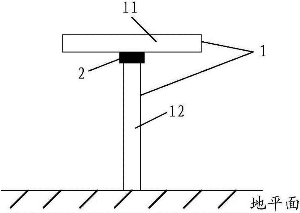
[0031] See image 3 As shown, the embodiment of the present invention provides a decoupling device, which adopts a ground branch structure and is arranged between two antennas.

[0032] Wherein, the decoupling device includes a coupling unit 1 and a tunable unit 2. The coupling unit 1 includes a horizontal branch 11 and a vertical branch 12, the middle point of the horizontal branch 11 is connected to one end of the vertical branch 12, and the other end of the v...


PUM


Abstract

The present invention provides a decoupling device. The decoupling device is disposed between two antennas and comprises a coupling unit and a tunable unit; the coupling unit comprises a horizontal branch and a vertical branch; the intermediate point of the horizontal branch is connected with one end of the vertical branch; the other end of the vertical branch is grounded; and the tunable unit is disposed on the coupling unit and is use for changing the electrical length of the horizontal branch of the coupling unit. With the decoupling device provided by the present invention adopted, the problem of mutual coupling between the multi-band antennas can be solved, a plurality of frequency bands can be decoupled, and the performance of the antennas can be improved.

Description

technical field [0001] The present invention relates to the technical field of antennas, in particular to a decoupling device. Background technique [0002] At present, when solving the mutual coupling problem between antennas in a handheld mobile terminal, a ground branch structure is often used for decoupling. [0003] Specifically, see figure 1 and figure 2 As shown, a simplified single-stage antenna is used to illustrate the method of ground branch decoupling. see figure 1 As shown, the two monopole antennas (i.e. monopole antenna A and monopole antenna B) are parallel to each other, and the distance is relatively close. In the actual implementation, the electrical length of the two monopole antennas is λ / 4, and the two The pole antennas are the same length. In this way, there is relatively large mutual coupling directly between the two antennas. If the monopole antenna A is fed with a sinusoidal signal, the current on it is I1; since the monopole antenna B is clo...

Claims


Application Information

Patent Timeline
IPC IPC(8): H01Q1/50H01Q1/52
CPCH01Q1/50H01Q1/52H01Q1/521
Inventor 刘锋昱
Owner ZTE CORP
Why Eureka
Try Eureka