Shift Register
A technology of shift register and potential, which is applied in static memory, digital memory information, instruments, etc., and can solve problems such as misoperation of shift registers
- Summary
- Abstract
- Description
- Claims
- Application Information
AI Technical Summary
Problems solved by technology
Method used
Image

Examples
no. 1 approach
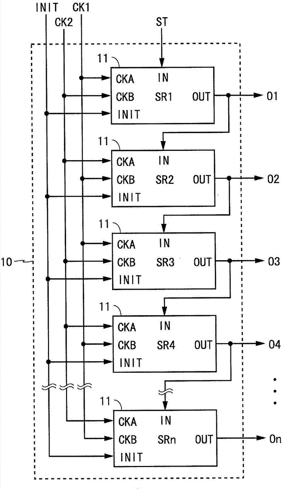
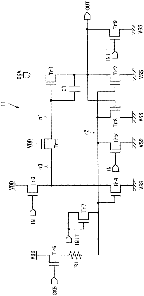
[0110]Hereinafter, a shift register according to an embodiment of the present invention will be described with reference to the drawings. In the following description, when the on-terminal of the transistor may be either the source terminal or the drain terminal, the fixed on-terminal of one will be referred to as the source terminal, and the fixed on-terminal of the other will be referred to as the fixed on-terminal of the other. Drain terminal. In addition, a signal input or output via a certain terminal is referred to by the same name as the terminal (for example, a signal input via the clock terminal CKA is referred to as a clock signal CKA). In addition, the potential that turns on the transistor when applied to the gate terminal is referred to as an ON potential, and the potential that turns off the transistor is referred to as an OFF potential. For example, for an N-channel transistor, a high-level potential is an on potential, and a low-level potential is an off poten...
no. 2 approach
[0136] Figure 4 It is a block diagram showing the structure of the shift register which concerns on the 2nd Embodiment of this invention. Figure 4 The illustrated shift register 20 has a configuration in which a function of switching the scanning direction (shift direction) is added to the shift register 10 according to the first embodiment. The shift register 20 includes n unit circuits 11 and n selection circuits 22 . The n unit circuits 11 and the n selection circuits 22 are provided in a one-to-one correspondence. Hereinafter, the selection circuit corresponding to the unit circuit Sri of the i-th stage is referred to as the selection circuit SELi of the i-th stage. The selection circuit 22 has input terminals IN1, IN2, control terminals UD, UDB, and an output terminal Z. The shift register 20 is externally supplied with a start signal ST, two-phase clock signals CK1 and CK2, an initialization signal INIT, and control signals UD and UDB. The control signal UDB is a n...
no. 3 approach
[0143] Image 6 It is a block diagram which shows the structure of the shift register which concerns on the 3rd Embodiment of this invention. Image 6 The illustrated shift register 30 has a configuration in which n unit circuits 31 are connected in multiple stages. The unit circuit 31 has an input terminal IN, clock signals CKA and CKB, an initialization terminal INIT, all-on control terminals AON and AONB, and an output terminal OUT. The shift register 30 is externally supplied with a start signal ST, two-phase clock signals CK1 and CK2, an initialization signal INIT, an all-on control signal AON, and a negative signal AONB of the all-on control signal (hereinafter, simply referred to as a negative signal AONB). ).
[0144] The start signal ST is supplied to the input terminal IN of the unit circuit 31 of the primary stage. The clock signals CK1 and CK2 and the initialization signal INIT are supplied to the n unit circuits 31 in the same manner as the shift register 10 ac...
PUM
 Abstract
Description
Claims
Application Information
 - R&D Engineer
- R&D Manager
- IP Professional
- Industry Leading Data Capabilities
- Powerful AI technology
- Patent DNA Extraction
Browse by: Latest US Patents, China's latest patents, Technical Efficacy Thesaurus, Application Domain, Technology Topic.
© 2024 PatSnap. All rights reserved.Legal|Privacy policy|Modern Slavery Act Transparency Statement|Sitemap