
Bicycle sprocket and bicycle sprocket assembly

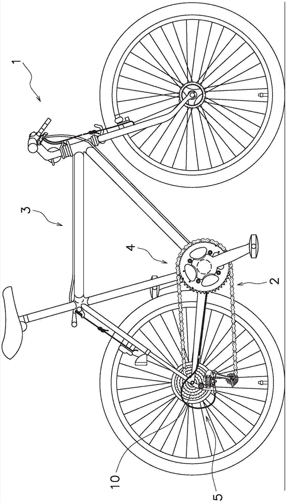
A bicycle and combination technology, applied in the direction of wheels, belts/chains/gears, vehicle parts, etc., can solve the problem of not being able to move, not the root of the teeth of another rear sprocket, etc., and achieve the effect of improving the speed change performance.

Active Publication Date: 2018-01-05
SHIMANO INC
View PDF10 Cites 0 Cited by
  • Summary
  • Abstract
  • Description
  • Claims
  • Application Information

AI Technical Summary

Problems solved by technology

For example, at the root of the tooth where the chain roller is difficult to move, when the chain roller is about to move from one rear sprocket to the other rear sprocket, the chain roller may first contact the sprocket tooth tip of the other rear sprocket, Instead of the root of the other rear sprocket, can't move smoothly from the root of one rear sprocket to the root of the other
Therefore, in the conventional sprocket, the position where the speed change operation can be performed is limited.

Method used


Image

  • Bicycle sprocket and bicycle sprocket assembly
  • Bicycle sprocket and bicycle sprocket assembly
  • Bicycle sprocket and bicycle sprocket assembly

Examples


no. 2 approach

[0116] Instead of the large-diameter rear sprocket 11 and the small-diameter rear sprocket 12 of the first embodiment, for Figure 7 The present invention can also be applied to the illustrated large-diameter rear sprocket 111 and small-diameter rear sprocket 112 (an example of a bicycle sprocket).

[0117] In the second embodiment, the dedendum portion 118 of the large-diameter rear sprocket 111 is composed of dedendum portions having the same shape over the entire circumference. In addition, the dedendum portion 128 of the small-diameter rear sprocket 112 is composed of a dedendum portion having a different shape.

[0118] In addition, in the second embodiment, descriptions of substantially the same configurations as those in the first embodiment are omitted. In addition, about the substantially same structure as 1st Embodiment, the same code|symbol as 1st Embodiment is attached|subjected.

[0119] (large diameter rear sprocket)

[0120] The large-diameter rear sprocket 111...


PUM


Abstract

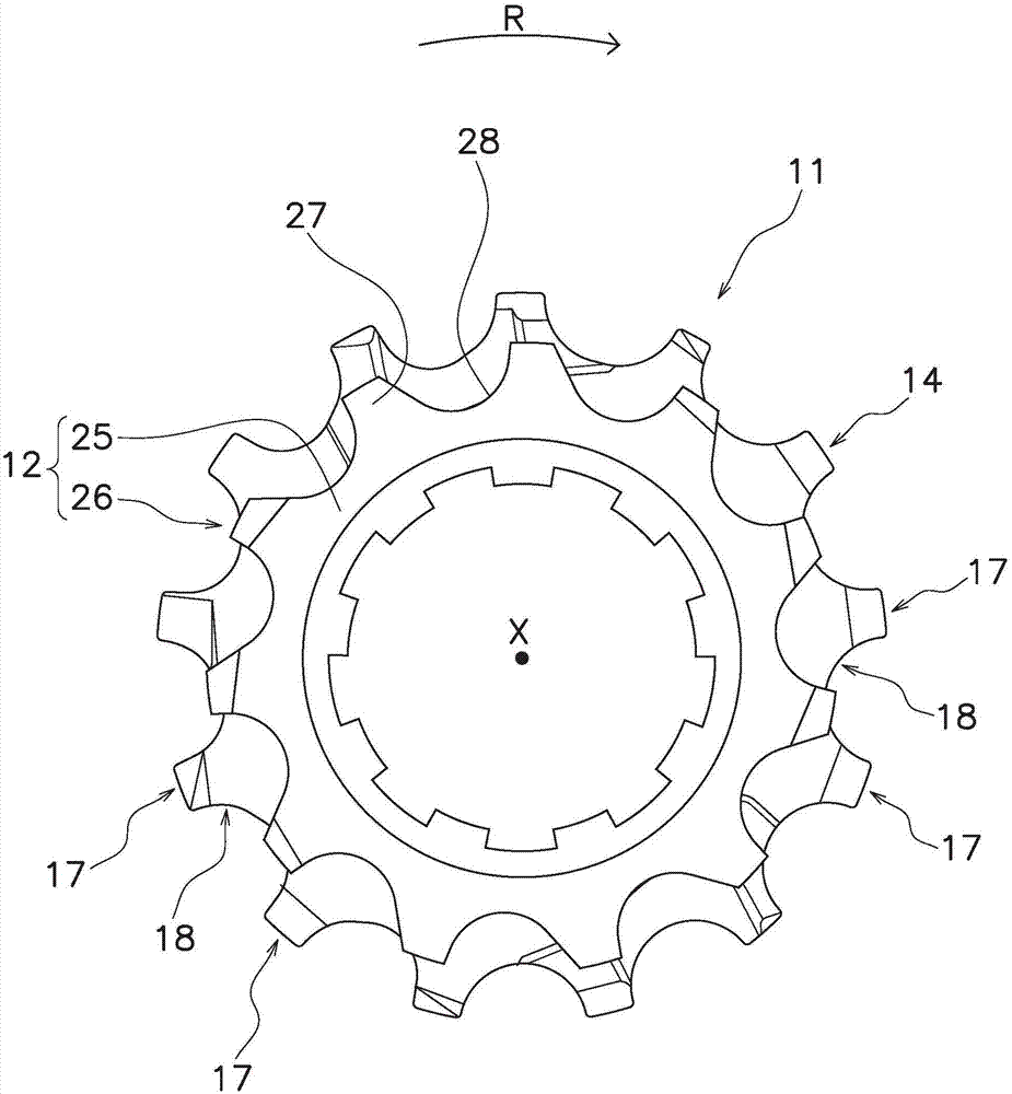
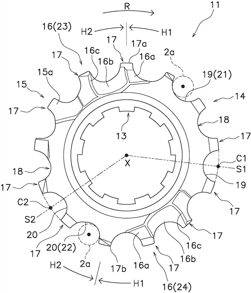
The invention provides a bicycle sprocket that can improve the degree of freedom of speed change operation. The bicycle sprocket includes a first sprocket body 3 and a plurality of first sprocket teeth 14. The first sprocket teeth 14 include a plurality of tooth tip portions 17 and a plurality of tooth bottom portions 18. The tooth bottom portions 18 include at least one first tooth bottom portion19 and at least one second tooth bottom portion 20. The at least one first tooth bottom portion 19 has a first tooth bottom shape. The at least one second tooth bottom portion 20 has a second tooth bottom shape. The first tooth bottom shape is different from the second tooth bottom shape.

Description

technical field [0001] The invention relates to a bicycle sprocket and a bicycle sprocket assembly. Background technique [0002] Conventional bicycle sprockets are provided separately on the crank assembly and the rear hub assembly. A bicycle chain is stretched between the front sprocket of the crank assembly and the rear sprocket of the rear hub assembly. Accordingly, the rotation of the crank assembly is transmitted to the rear hub assembly via the chain, whereby the rear wheel rotates. [0003] For example, the rear sprocket disclosed in Patent Document 1 is composed of a plurality of rear sprockets. [0004] Each rear sprocket is composed of an annular rear sprocket body and a plurality of rear sprocket teeth. A plurality of rear sprocket teeth respectively protrude radially outward from the rear sprocket body. A dedendum portion is formed between circumferentially adjacent rear sprocket teeth of the plurality of rear sprocket teeth. Here, each dedendum portion is ...

Claims


Application Information

Patent Timeline
Patent Type & Authority Applications(China)
IPC IPC(8): B62M9/10
CPCF16H55/08F16H55/0873B21K1/30B62M9/04B62M9/10B62M9/124
Inventor 蒲田建二
Owner SHIMANO INC
Learn More