
Inductive electromagnetic shock absorber

A shock absorber, inductive technology, used in springs/shock absorbers, magnetic springs, springs, etc., can solve problems such as large vibration and floating of vehicles

Inactive Publication Date: 2018-01-05
高强
View PDF0 Cites 0 Cited by
  • Summary
  • Abstract
  • Description
  • Claims
  • Application Information

AI Technical Summary

Problems solved by technology

[0003] The technical problem to be solved by the present invention is to provide an induction electromagnetic shock absorber, which can solve the problem of large vibration and fluctuation of vehicles

Method used


Image

  • Inductive electromagnetic shock absorber

Examples


Embodiment Construction

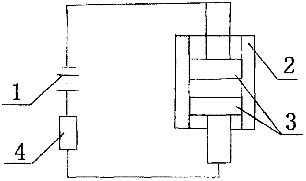
[0010] like figure 1 An inductive electromagnetic shock absorber includes a power supply 1, a conductor casing 2, a homosexual magnet 3, and a vibration detector 4. The same sex magnet 3 is in the conductor shell 2, the power supply 1, the vibration detector 4, and the conductor shell 2 are connected by electric wires.

[0011] The magnets are two magnets 3 with the same sex.

[0012] With the above-mentioned structure, when in use, by adopting the above-mentioned structure, the vibration detector changes the magnitude of the current according to the vibration amplitude of the vehicle after power-on and then transmits it to the same-sex magnet, and the same-sex magnet changes the magnetic magnitude according to the magnitude of the current to achieve the effect of vibration reduction.


PUM


Abstract

An inductive electromagnetic shock absorber includes a power supply, a conductor casing, a magnet of the same sex, and a vibration detector. The same-sex magnet is in the conductor shell, the power supply, the vibration detector, and the conductor shell are connected by wires. After electrification, the vibration detector changes the magnitude of the current according to the vibration amplitude of the vehicle and then transmits it to the same-sex magnet. The same-sex magnet changes the magnetic magnitude according to the magnitude of the current to achieve the effect of vibration reduction. The device is set on the tire of the vehicle.

Description

technical field [0001] The invention belongs to the field of living equipment, and in particular relates to an induction electromagnetic shock absorber. Background technique [0002] The existing vehicle damping device still has the disadvantages of large vibration amplitude and the like. Contents of the invention [0003] The technical problem to be solved by the present invention is to provide an induction electromagnetic shock absorber, which can solve the problem of large vibration fluctuation of the vehicle. [0004] In order to solve the problems of the technologies described above, the technical solution adopted in the present invention is: [0005] An inductive electromagnetic shock absorber includes a power supply, a conductor casing, a magnet of the same sex, and a vibration detector. The same-sex magnet is in the conductor shell, the power supply, the vibration detector, and the conductor shell are connected by wires. [0006] The above-mentioned magnets are ...

Claims


Application Information

Patent Timeline
IPC IPC(8): F16F6/00
Inventor 高强
Owner 高强
Learn More