Converter valve fire extinguishing device

A technology of fire extinguishing device and converter valve, which is applied in fire rescue and other directions, can solve the problems of personal safety threat and low degree of automation, and achieve the effect of wide fire extinguishing range, improving fire extinguishing efficiency, and avoiding the spread of fire.

Inactive Publication Date: 2018-01-09
XJ ELECTRIC +2
View PDF11 Cites 11 Cited by
  • Summary
  • Abstract
  • Description
  • Claims
  • Application Information

AI Technical Summary

Problems solved by technology

However, the above method still requires staff to conduct on-site inspections and on-site fire fighting, which not only has a low degree of automation, but also poses a certain threat to personal safety.

Method used


Image

  • Converter valve fire extinguishing device
  • Converter valve fire extinguishing device
  • Converter valve fire extinguishing device

Examples


Embodiment 1

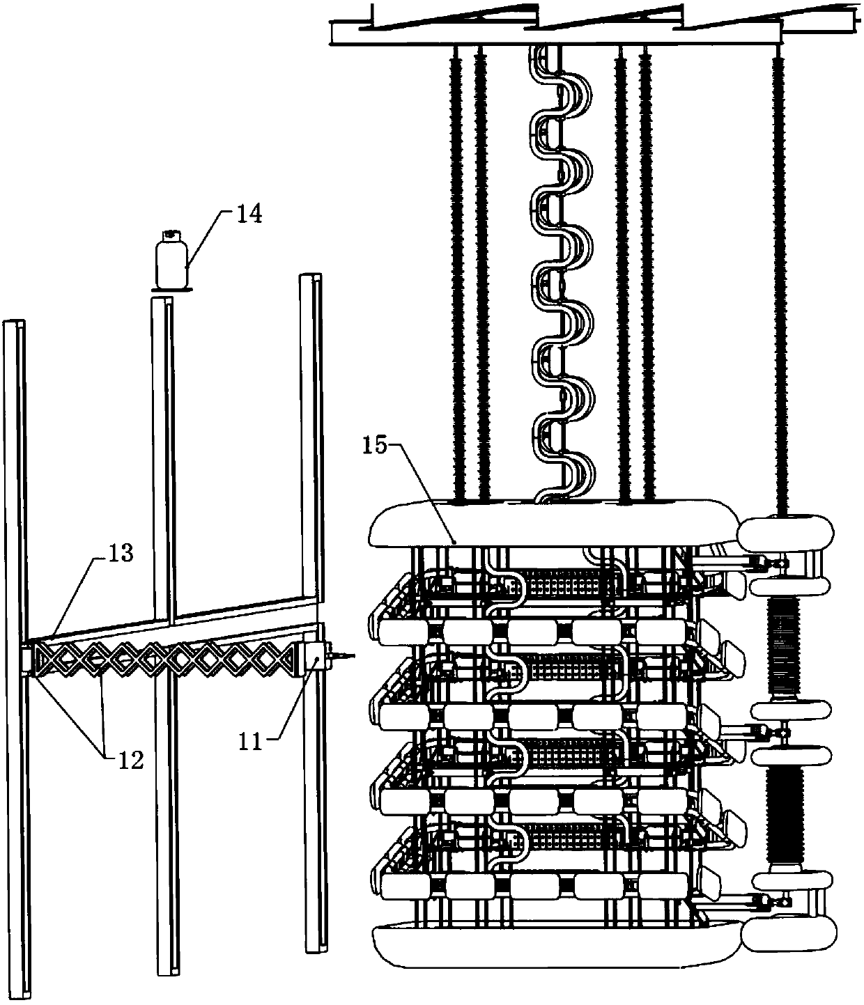
[0040] Such as Figure 4 , 5 As shown, the fire extinguishing device guide rail 13 is a side-mounted rail frame, and the side-mounted rail frame is in a side-mounted plane. The side-mounted plane is perpendicular to the horizontal plane and includes a first rail 31 arranged horizontally. A motion mechanism 32, the first motion mechanism 32 is provided with a second track 33, the second track 33 is provided with a second motion mechanism 34 for guiding movement, and the second track 33 and the first track 31 are intersected in a lateral plane. The shapes of the first track 31 and the second track 33 are not fixed, for example, they may be linear, curved, etc. The second movement mechanism 34 is connected with a hydraulic-mechanical telescopic mechanism 12 and a driving mechanism for driving the telescopic mechanism to expand or contract. The hydraulic-mechanical telescopic mechanism 12 drives the fire extinguishing device injection terminal 11 provided at its end.

[0041] Fi...

Embodiment 2

[0043] Such as Figure 6 As shown, the guide rail 13 of the fire extinguishing device is a side-mounted track frame, and the side-mounted track frame is in a side-mounted plane. The side-mounted plane is perpendicular to the horizontal plane and includes at least two rails arranged crosswise. A movement mechanism 41 is provided for guiding movement on the rails. The movement mechanism 41 is connected with a hydraulic mechanical telescopic mechanism 12 and a driving mechanism that drives the hydraulic mechanical telescopic mechanism 12 to expand or contract. The hydraulic mechanical telescopic mechanism 12 drives the fire extinguishing device injection terminal 11 provided at its end. The shape of these tracks is also not fixed, and can be straight, curved or the like.

[0044] Driven by the driving mechanism, the spray terminal 11 of the fire extinguishing device can move freely along the track. Such as Figure 6 As shown, move to the dotted line position in the figure along...


PUM


Abstract

The invention relates to a converter valve fire extinguishing device comprising a side-mounted track frame, fire bottles used for storing fire extinguishing agents, and a control module used for acquiring a fire position; the side-mounted track frame is located in a side-mounted plane vertical to a horizontal plane, and the side-mounted track frame comprises at least two crossover tracks which aremovably provided with movement mechanisms in a guiding way; the movement mechanisms are connected to telescoping mechanisms, and driving mechanisms used for driving the telescoping mechanisms to extend or contract, and the telescoping mechanisms are used for driving fire extinguishing terminals arranged at the ends of the telescoping mechanisms; and the fire extinguishing terminals comprise fireextinguishing nozzles connected to the fire bottles through pipes. In the converter valve fire extinguishing device, according to the corresponding positions of fire points, the fire extinguishing terminals rotatably connected to the telescoping mechanisms are driven by the telescoping mechanisms moving along the set tracks to move to proper positions for extinguishing the fire points, so that thefire extinguishing terminals can reach all positions of different valve towers.

Description

technical field [0001] The invention belongs to the technical field of fire safety, and in particular relates to a converter valve fire extinguishing device. Background technique [0002] The converter valve is the core equipment of the direct current transmission project, and its main function is to rectify alternating current into direct current or invert direct current into alternating current. The safe and reliable operation of the converter valve is directly related to the reliable operation of the entire DC transmission system. With the continuous improvement of the transmission capacity of DC transmission projects, the requirements for its reliability and availability are also increasing. Moreover, its cost accounts for about 22-25% of the total cost of the complete equipment of the converter station. [0003] The main causes of converter valve fires in engineering include: weak connection / high resistance connection, valve component failure, thyristor level connecti...

Claims


Application Information

Patent Timeline
IPC IPC(8): A62C3/16A62C37/42
Inventor 周云宏范彩云韩坤刘堃魏卓杜玉格毛文喜王晓民
Owner XJ ELECTRIC
Why Eureka
Try Eureka