Comprehensive stirring machine

A technology for mixers and stirring blades, which is applied to mixers, mixers with rotating stirring devices, dissolution, etc., can solve the problems of single structure of stirring blades, and achieve the effect of improving stirring efficiency and promoting stirring

Inactive Publication Date: 2018-01-09
江门市丰溢电器制造有限公司
3 Cites 1 Cited by

AI-Extracted Technical Summary

Problems solved by technology

[0004] The problem to be solved by the present invention is the problem...

Abstract

The invention relates to a comprehensive stirring machine which comprises a shell, a stirring paddle, a pull rope, stirring balls, a base, a motor, a feeding port, a second fish eye bearing, a stirring blade, a stirring shaft, hollow parts, a first fish eye bearing, flange bearings, a rotating shaft, stirring plates, support legs and a blanking port, wherein the base is arranged on the left side of the shell; the motor is arranged on the base; the motor is connected with the rotating shaft through a coupler; left and right ends of the rotating shaft are respectively arranged on the flange bearings; the flange bearings are arranged on left and right sides in the shell; the stirring plates are respectively arranged on upper and lower sides of the stirring shaft; the hollow parts are arrangedin the stirring plates; two stirring balls are arranged in the hollow parts. The comprehensive stirring machine has the advantage that the stirring mechanism has various structures.

Application Domain

Rotary stirring mixers

Technology Topic

FlangeFish eye +2

Image

  • Comprehensive stirring machine
  • Comprehensive stirring machine
  • Comprehensive stirring machine

Examples

  • Experimental program(1)

Example Embodiment

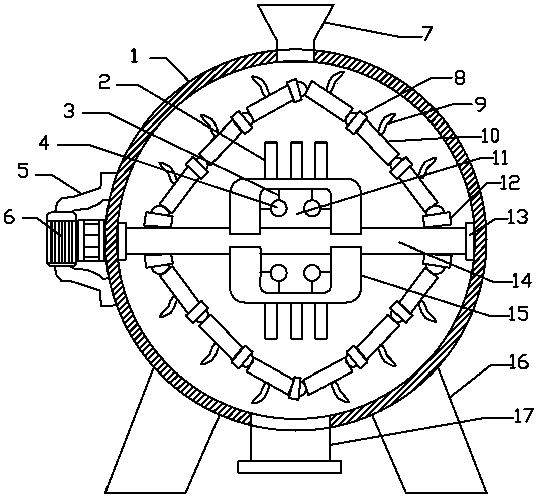
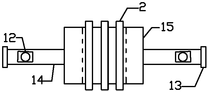
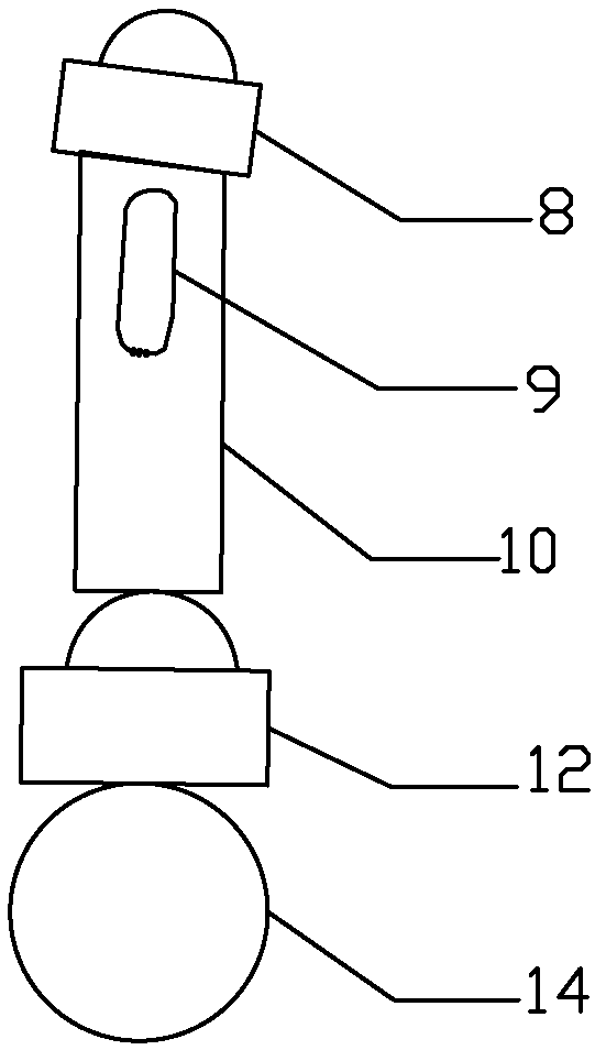
[0015] The present invention will be further described below with reference to the drawings and embodiments.
[0016] The integrated mixer of the present invention includes a casing 1, a mixing blade 2, a drawstring 3, a mixing ball 4, a base 5, a motor 6, a feed port 7, a second fisheye bearing 8, a mixing blade 9, a mixing shaft 10, and a hollow 11. The first fisheye bearing 12, the flange bearing 13, the rotating shaft 14, the mixing plate 15, the support leg 16 and the discharge opening 17, the left side of the casing 1 is installed with a base 5, and a motor 6 is installed on the base 5. The motor 6 is connected to the rotating shaft 14 through a coupling. The left and right ends of the rotating shaft 14 are installed on flange bearings 13 respectively. The flange bearings 13 are installed on the left and right sides of the casing 1, and the upper and lower sides of the mixing shaft 10 are equipped with mixing plates 15 respectively. , The stirring plate 15 is provided with a hollow 11, and there are two stirring balls 4 in the hollow 11, a drawstring 3 is installed on the top and left of the stirring ball 4, and the other end of the drawstring 3 is connected to the stirring plate 15, and the stirring plate 15 follows During the rotation of the rotating shaft 14, the stirring ball 4 swayed from side to side under the pull rope 3 to promote stirring. The draw rope 3 is shorter, so that the draw rope 3 will not be entangled on the stirring plate 15 or two The mixing balls 4 are entangled with each other; a plurality of mixing blades 2 are installed on the mixing plate 15, the left and right sides of the rotating shaft 14 are respectively installed with first fisheye bearings 12, and two adjacent mixing shafts 10 are connected end to end through the second fisheye bearings 8. Together to form a stirring chain, the rotation of the rotating shaft 14 drives the stirring chain and the sliding stirring blade 9 to rotate, the stirring shaft 10 is connected end to end through the second fisheye bearing 8 to form a stirring chain, the stirring shaft 10 can rotate with the second fisheye bearing 8 Swing so that the stirring chain can shake. The stirring chain rotates under the drive of the shaft 14. The speed of the shaft 14 becomes larger or smaller, and the stirring chain will shake with the speed to promote the stirring of the liquid; the left and right ends of the stirring chain are installed on the first On a fisheye bearing 12, the mixing shaft 10 is hingedly mounted with mixing blades 2, the housing 1 is equipped with a feed inlet 7, and the bottom of the housing 1 is equipped with a discharge opening 17, and the housing 1 is installed on the leg 16, and the feed The inlet 7 is equipped with a feed valve, and the discharge inlet 17 is equipped with a discharge valve. The drawstring 3 is a nylon rope. The mixing structure composed of the mixing chain, the mixing blade 2, the mixing ball 4 and the mixing plate 15 can solve the prior art The mixing blade 2 of the mixer is too simple, which can improve the mixing efficiency. The motor uses the Juhao Y2100L2-4YL100L2 mixer motor.
[0017] The method of use of the present invention: the rotation of the rotating shaft 14 drives the stirring chain and the sliding stirring blade 9 to rotate, the stirring shaft 10 is connected end to end through the second fisheye bearing 8 to form a stirring chain, and the stirring shaft 10 can rotate and swing with the second fisheye bearing 8. The stirring chain can be shaken. The stirring chain rotates under the drive of the rotating shaft 14. When the rotating shaft 14 rotates larger or smaller, the stirring chain will shake with the rotating speed to promote the stirring of the liquid; while the stirring plate 15 rotates with the rotating shaft 14, The stirring ball 4 swayed from side to side under the pull of the drawstring 3 to promote stirring, and the drawstring 3 is short, so that the drawstring 3 will not be entangled on the stirring plate 15 and the two stirring balls 4 will not be entangled with each other. The stirring structure composed of the stirring chain, the stirring blade 2, the stirring ball 4 and the stirring plate 15 can solve the problem that the stirring and stirring blades 2 of the prior art mixer are too simple, and can improve the stirring efficiency.

PUM

no PUM

Description & Claims & Application Information

We can also present the details of the Description, Claims and Application information to help users get a comprehensive understanding of the technical details of the patent, such as background art, summary of invention, brief description of drawings, description of embodiments, and other original content. On the other hand, users can also determine the specific scope of protection of the technology through the list of claims; as well as understand the changes in the life cycle of the technology with the presentation of the patent timeline. Login to view more.

Similar technology patents

Jet flow stirring kettle and use method thereof

Owner:ACRE COKING & REFRACTORY ENG CONSULTING CORP DALIAN MCC

Height-adjustable wear-resistant anchor type stirring paddle

InactiveCN104001447APrevent material from splashingpromote stirring
Owner:周鹏

Stirrer for glass fiber reinforced plastic septic tank

PendingCN112028430AIncrease operating powerImprove stirring efficiency
Owner:邵阳千两新型环保建材有限公司

Viscous fine mineral powder fluidization reactor

InactiveCN103752232Apromote stirringEnhanced heat transfer
Owner:CHONGQING UNIV

Classification and recommendation of technical efficacy words

  • promote stirring
  • Improve stirring efficiency

Height-adjustable wear-resistant anchor type stirring paddle

InactiveCN104001447APrevent material from splashingpromote stirring
Owner:周鹏

Viscous fine mineral powder fluidization reactor

InactiveCN103752232Apromote stirringEnhanced heat transfer
Owner:CHONGQING UNIV

Antihypertensive drug production equipment

ActiveCN108211889Aincrease the relative rotational speedImprove stirring efficiency
Owner:安徽颐生堂中药饮片有限公司

Vibratory self-circulating paint mixer

InactiveCN108579572AImprove stirring efficiencyPaint sprayed evenly
Owner:东莞市国新智造产业孵化器有限公司
Why Eureka
Try Eureka