
Heat-storage heating equipment for heating by using gas

A gas heating and heat storage technology, which is applied to lighting and heating equipment, central heating, and can solve problems such as environmental hazards of coal heating

Active Publication Date: 2018-01-12
天津天爱环保技术开发有限公司
View PDF7 Cites 1 Cited by
  • Summary
  • Abstract
  • Description
  • Claims
  • Application Information

AI Technical Summary

Problems solved by technology

[0002] In recent years, with the rapid development of society and the continuous improvement of human living standards, central heating has become a very popular thing in people's life and work in northern cities in my country. At present, the traditional heating mainly uses coal heating. Or electric heating. As we all know, coal heating solves the problem of heating to a certain extent, but because coal heating will cause great environmental hazards. Therefore, in recent years, with the increasingly severe environmental problems, electric heating has gradually replaced Coal is used for heating, but it is obvious that a large part of electric energy is also generated by coal. These measures only remove the pollution source from the big cities, but for the remote areas of coal power generation, the pollution still exists. Therefore, how to design and develop a A kind of gas heating heat storage heating equipment that can solve the above problems is particularly important.

Method used


Image

  • Heat-storage heating equipment for heating by using gas
  • Heat-storage heating equipment for heating by using gas
  • Heat-storage heating equipment for heating by using gas

Examples


Embodiment Construction

[0039] In order to further understand the content, features, and effects of the present invention, the following embodiments are exemplified and described in detail with the accompanying drawings as follows:

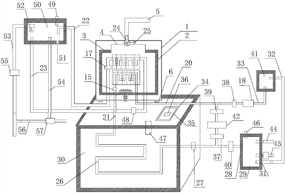
[0040] See Figure 1 to Figure 6 , A gas-fired heat storage heating equipment, including:

[0041] A phase change material heat storage tank 30 containing a phase change material inside. The phase change material heat storage tank 30 is provided with a heat transfer oil tube 26; the top of the phase change material heat storage tank 30 is provided with a feeding port 34. A feeding opening cover 35 is installed at the position of the feeding opening 34, and a feeding box exhaust hole 36 is opened on the feeding opening cover 35;

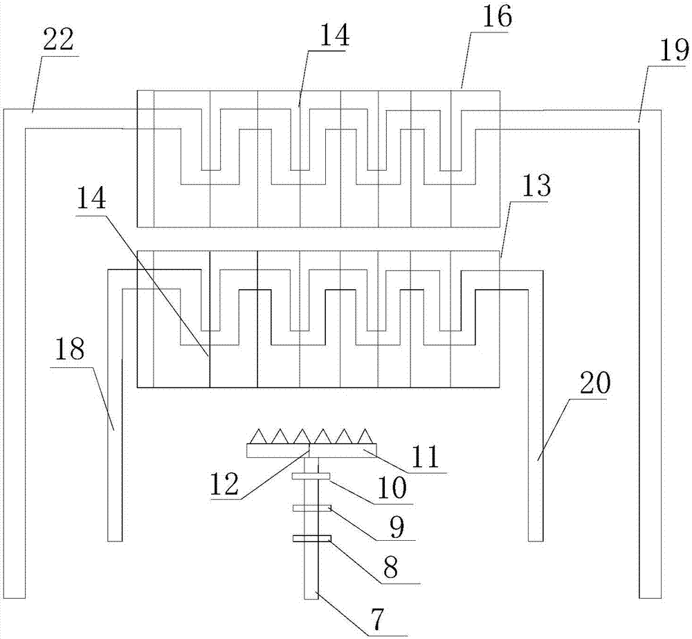
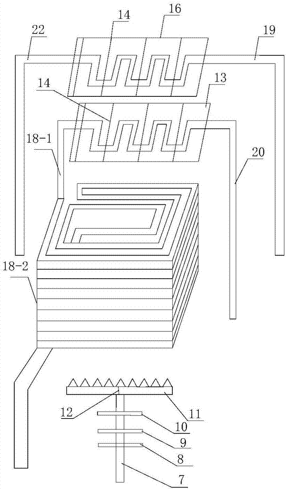
[0042] A heating box, which is provided with a water heater 16, an oil heater 13, and a gas heating device;

[0043] Water storage tank 50, oil storage tank 41 and heating and heat exchange tank 29; among them:

[0044] The water heater 16 communicates ...


PUM


Abstract

The invention discloses heat-storage heating equipment for heating by using gas. The equipment comprises a phase-change material heat storage box, a heating box, a water storage tank, an oil storage tank and a heating and heat-exchanging box, wherein a heat-conduction oil heat exchange tube is arranged in the phase-change material heat storage box; a water heater, an oil heater and a gas heating device are arranged in the heating box; the water heater is connected with the water storage tank through a water circulation pipeline; an oil liquid outlet of the oil storage tank is successively connected with a liquid inlet end of a heat-conduction oil circulation tube through a heat-conduction oil discharging and circulating tube; a liquid outlet end of the heat-conduction oil circulation tubepasses through the oil heater and is subsequently connected with the inlet of the heat-conduction oil heat exchange tube of the phase-change material heat storage box; the outlet of the heat-conduction oil heat exchange tube of the phase-change material heat storage box is connected with the heating and heat-exchanging box; the inlet of the heat-conduction oil heat exchange tube is connected withthe outlet of the heat-conduction oil heat exchange tube through the heat-conduction oil heat exchange tube; the heating and heat-exchanging box is connected with the oil storage tank through a heat-conduction oil returning and circulating tube; a forced circulation pump is mounted in the water circulation pipeline; a heat-conduction oil main circulation pump is mounted on the heat-conduction oilcirculation tube or the heat-conduction oil returning and circulating tube.

Description

Technical field [0001] The invention relates to the technical field of heating equipment, in particular to a gas-fired heat storage heating equipment. Background technique [0002] In recent years, with the rapid development of society and the continuous improvement of human living standards, in northern cities in China, central heating has become a very popular thing in people’s life and work. At present, traditional heating mainly uses coal heating. Or electric heating. As we all know, coal heating can solve the heating problem to a certain extent. However, because coal heating can cause great environmental damage, in recent years, as environmental problems have become increasingly severe, electric heating has gradually replaced Coal is used for heating, but it is obvious that a large part of electricity generation is also coal for power generation. These measures only remove pollution sources from large cities, but for remote areas of coal power generation, pollution still exi...

Claims


Application Information

Patent Timeline
IPC IPC(8): F24D11/00F24D19/10F24D19/00
Inventor 刘祥宇
Owner 天津天爱环保技术开发有限公司
Learn More