
Optical module group assembling device

A technology for assembling equipment and equipment, used in optics, optical components, installation, etc., to solve problems such as errors and affecting the optical performance of optical modules

Active Publication Date: 2018-01-16
GOERTEK OPTICAL TECH CO LTD
View PDF14 Cites 6 Cited by
  • Summary
  • Abstract
  • Description
  • Claims
  • Application Information

AI Technical Summary

Problems solved by technology

However, there are large errors in these assembly methods, which affect the optical performance of the assembled optical module

Method used


Image

  • Optical module group assembling device
  • Optical module group assembling device
  • Optical module group assembling device

Examples


Embodiment Construction

[0027] In order to make the purpose, technical solution and advantages of the present invention clearer, the technical solution of the present invention will be clearly and completely described below in conjunction with specific embodiments of the present invention and corresponding drawings. Apparently, the described embodiments are only some of the embodiments of the present invention, but not all of them. Based on the embodiments of the present invention, all other embodiments obtained by persons of ordinary skill in the art without making creative efforts belong to the protection scope of the present invention.

[0028] It should be noted that, in the following embodiments of the present invention, the optical module refers to the complete product after alignment is completed and fixed; the optical module to be aligned refers to the optical module in the assembly process, which It may be in a misaligned state or in an aligned state; the optical part to be assembled refers ...


PUM


Abstract

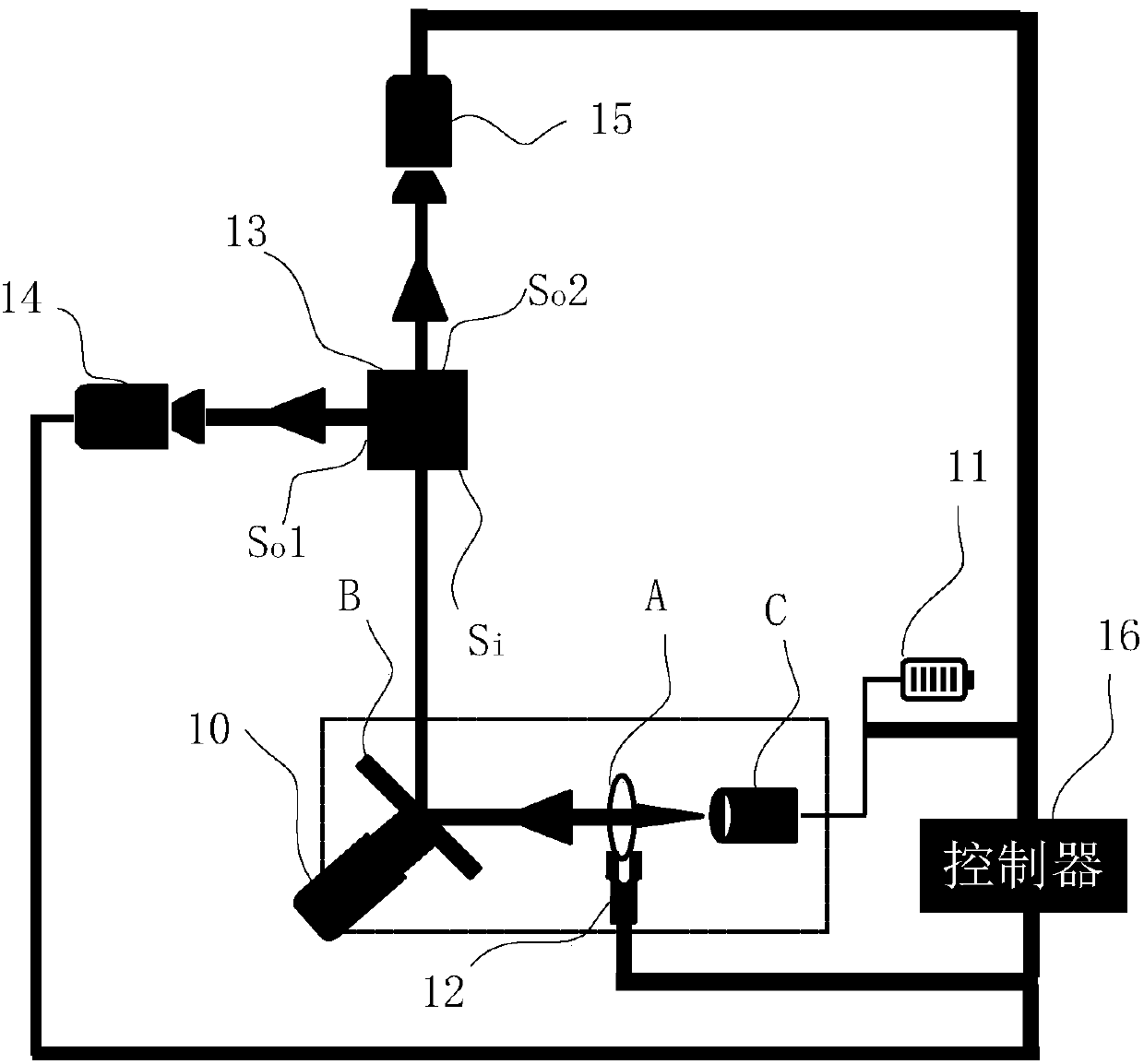
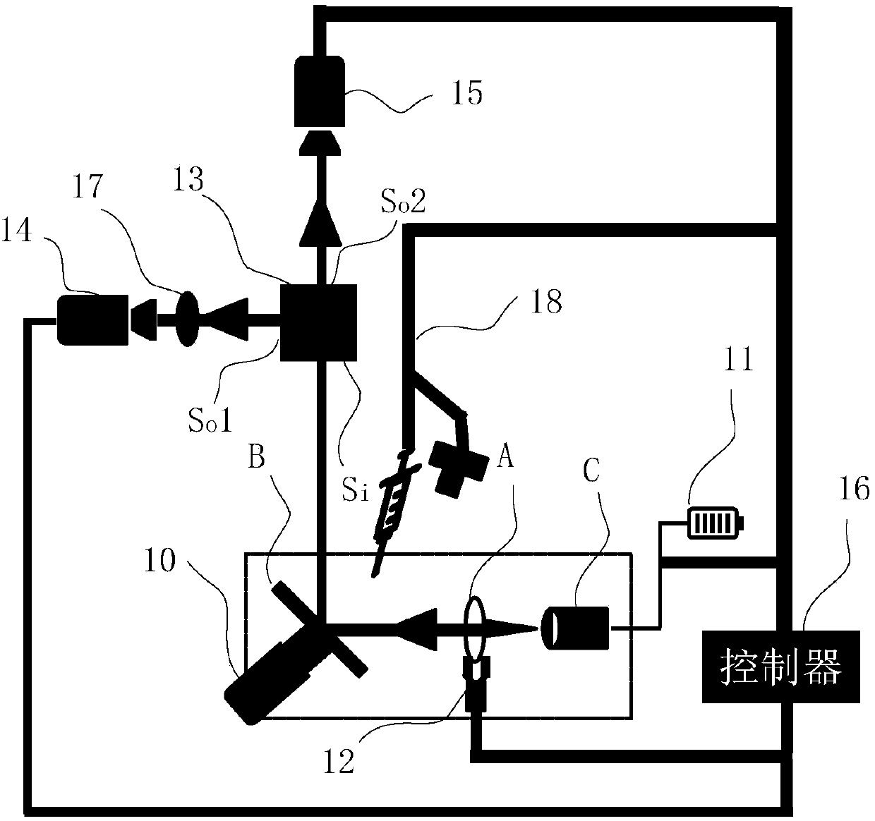
The invention provides an optical module group assembling device comprising a fixing member used for fixing an optical member to be assembled, a power source assembly used for supplying electric powerto the optical member to be assembled, an aligning mechanism used for placing lenses to be assembled at a designated position for the assembled optical member, a light splitting prism of which a light receiving face is positioned close to an optical device to be assembled, a first image collection device positioned close to a first light emitting face of the light splitting prism, a second imagecollection device positioned close to a second light emitting face of the light splitting prism, and a controller used for controlling the aligning mechanism to adjust positions of lenses to be assembled according to photos taken via the first image collection device and the second image collection device, wherein the first image collection device and the first light emitting face are coaxial, andthe second image collection device and the second light emitting face are coaxial. Via the device provided in the invention, assembling allowance of an optical module group can be lowered, and optical performance of the optical module group can be effectively improved.

Description

technical field [0001] The invention relates to the field of assembly technology, in particular to an optical module assembly equipment. Background technique [0002] Nowadays, there are more and more optical modules with independent functions in the market to meet the diverse market demands. These optical modules can be embedded in other devices to play their functions, such as camera modules, micro projection modules, LED (Light Emitting Diode, light emitting diode) optical modules and VR (Virtual Reality, virtual reality) / AR (Augmented Reality , augmented reality) optical modules, etc. [0003] Usually, an optical module is assembled from multiple optical elements and other parts. For example, a camera module can be assembled from spare parts such as an image sensor, a lens mount, multiple lenses, and a circuit board. Among them, the assembly accuracy of the lens plays a decisive role in the optical performance of the optical module. [0004] In the prior art, the l...

Claims


Application Information

Patent Timeline
Patent Type & Authority Applications(China)
IPC IPC(8): G02B27/62
CPCG02B27/62G02B7/005G02B7/023G02B7/025G02B27/0977G02B27/123
Inventor 董南京孙德波
Owner GOERTEK OPTICAL TECH CO LTD
Learn More