Workpiece stamping device with clamping function

A technology for stamping devices and workpieces, applied in the directions of feeding devices, positioning devices, storage devices, etc., can solve the problems of low work efficiency, low workpiece clamping stability, and small application scope, so as to improve the clamping quality, enhance the The effect of stability and improving work efficiency

Inactive Publication Date: 2018-01-19
ANHUI HAITUO ZHIYONG INTELLIGENT EQUIP CO LTD
View PDF5 Cites 2 Cited by
  • Summary
  • Abstract
  • Description
  • Claims
  • Application Information

AI Technical Summary

Problems solved by technology

[0003] The purpose of the present invention is to provide a high-efficiency, high-efficiency, workpiece-clamping process that exists in the existing workpiece stamping device in the process of clamping the workpiece. A workpiece stamping device with a clamping function that has good force uniformity, high workpiece clamping stability, and a wide range of applications

Method used


Image

  • Workpiece stamping device with clamping function
  • Workpiece stamping device with clamping function

Examples


Embodiment 1

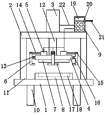
[0014] as attached figure 1 As shown, a workpiece stamping device with a clamping function includes a bottom plate 1, a top plate 2, a cylinder one 3, a connecting plate 4, a cylinder two 5, an adjustment block 6, a stamping block 7, a lower pad 8 and a controller 9, It is characterized in that: the bottom plate 1 is set on the bracket 10, and a column 11 is set on the bottom plate 1, the top plate 2 is set on the column 11, the cylinder one 3 is set on the top plate 2, and Cylinder one 3 is provided with piston rod one 12, described connecting plate 4 is arranged on the piston rod one 12, and connecting block 13 is arranged on connecting plate 4, described cylinder two 5 is arranged on connecting plate 4, And on cylinder two 5, be provided with piston rod two 14, described adjusting block 6 one ends are connected with piston rod two 14 by bearing pin 15, and limit rod 16, clamping rod 17 are set on adjusting block 6, described The stamping block 7 is arranged on the connecti...

Embodiment 2

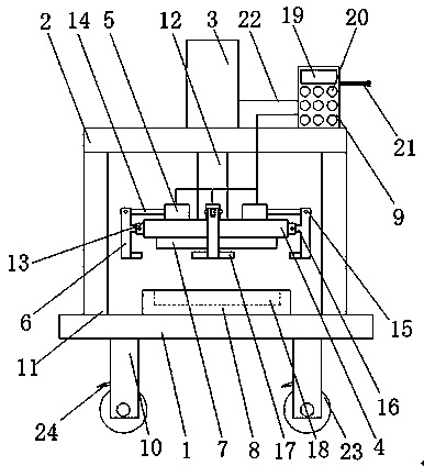
[0018] as attached figure 2 As shown, a workpiece stamping device with a clamping function includes a bottom plate 1, a top plate 2, a cylinder one 3, a connecting plate 4, a cylinder two 5, an adjustment block 6, a stamping block 7, a lower pad 8 and a controller 9, It is characterized in that: the bottom plate 1 is set on the bracket 10, and a column 11 is set on the bottom plate 1, the top plate 2 is set on the column 11, the cylinder one 3 is set on the top plate 2, and Cylinder one 3 is provided with piston rod one 12, described connecting plate 4 is arranged on the piston rod one 12, and connecting block 13 is arranged on connecting plate 4, described cylinder two 5 is arranged on connecting plate 4, And on cylinder two 5, be provided with piston rod two 14, described adjusting block 6 one ends are connected with piston rod two 14 by bearing pin 15, and limit rod 16, clamping rod 17 are set on adjusting block 6, described The stamping block 7 is arranged on the connect...


PUM


Abstract

Disclosed is a workpiece stamping device with a clamping function. The workpiece stamping device with the clamping function comprises a base plate, a top plate, a first air cylinder, a connecting plate, second air cylinders, adjusting blocks, stamping blocks, a lower cushion block and a controller. The workpiece stamping device with the clamping function is characterized in that the base plate isarranged on a support, the top plate is arranged on stand columns, and the first air cylinder is arranged on the top plate; and the connecting plate is arranged on a first piston rod, the second air cylinders are arranged on the connecting plate, one end of each adjusting block is connected with a second piston rod through a hinge pin, and the stamping blocks are arranged on the connecting plate.According to the workpiece stamping device with the clamping function, the second air cylinders and a plurality of connecting blocks are arranged on the connecting plate, the connecting blocks are connected with limiting rods on the adjusting blocks through the hinge pins, the adjusting blocks are connected with the second piston rods through the hinge pins, after stamping of a workpiece is accomplished, the second air cylinders and the second piston rods push the adjusting blocks to enable clamping rods on the adjusting blocks to clamp the workpiece, and therefore the clamping quality of theworkpiece is improved, the stability of the workpiece in the clamping process is enhanced, and then the working efficiency is improved.

Description

technical field [0001] The invention relates to the field of workpiece processing, in particular to a workpiece stamping device with a clamping function. Background technique [0002] At present, in the process of workpiece processing, it is often necessary to stamp the workpiece. After the workpiece is stamped, it is difficult to remove the mold. For example, the patent application number 201621368510.5 discloses a stamping press with synchronous clamping function. The problem of workpiece displacement during clamping is solved, but it has the disadvantages of low work efficiency, low stability of workpiece clamping and small application range. Contents of the invention [0003] The purpose of the present invention is to provide a high-efficiency, high-efficiency, workpiece-clamping process that exists in the existing workpiece stamping device in the process of clamping the workpiece. The workpiece stamping device with clamping function has good force uniformity, high wo...

Claims


Application Information

Patent Timeline
Patent Type & Authority Applications(China)
IPC IPC(8): B21D43/00
Inventor 冯继友梁振华
Owner ANHUI HAITUO ZHIYONG INTELLIGENT EQUIP CO LTD
Why Eureka
Try Eureka