Clamping structure of industrial robot

A technology of industrial robots and clamping structures, applied in chucks, manipulators, manufacturing tools, etc., can solve problems such as low firmness of workpieces, poor processing quality, and small application range, so as to improve clamping quality and work efficiency , the effect of improving stability

Inactive Publication Date: 2018-11-13
WUHU DEJIA INTELLIGENT TECH CO LTD
View PDF0 Cites 0 Cited by
  • Summary
  • Abstract
  • Description
  • Claims
  • Application Information

AI Technical Summary

Problems solved by technology

[0003] The purpose of the present invention is to overcome the problems of poor versatility, small scope of application, and poor processing quality due to the low firmness of the workpiece on the clamping structure existing in the existing industrial robot clamping structure, and to provide a kind of structure design that is reasonable, and the workpiece is placed on the clamping structure. The clamping structure of industrial robots with high firmness, high work efficiency and wide application range

Method used


Image

  • Clamping structure of industrial robot
  • Clamping structure of industrial robot
  • Clamping structure of industrial robot

Examples


Embodiment 1

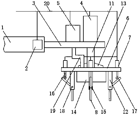
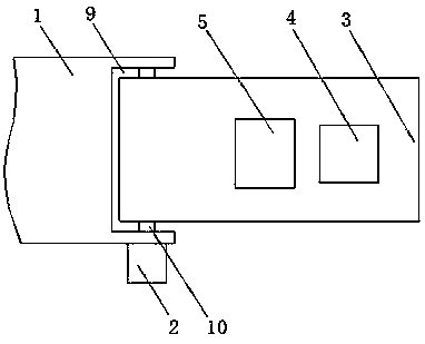
[0019] as attached figure 1 with 2 As shown, a clamping structure of an industrial robot includes a positioning plate 1, a motor 2, a load plate 3, a cylinder one 4, a vacuum pump 5, a fixed plate 6, a cylinder two 7 and a clamping rod 8, and is characterized in that: The positioning plate 1 is provided with a limiting groove 9, the motor 2 is arranged on the positioning plate 1, a rotating shaft 10 is arranged on the motor 2, and the rotating shaft 10 is arranged in the limiting groove 9, the described One end of the bearing plate 3 is connected with the rotating shaft 10, the cylinder one 4 is arranged on the bearing plate 3, and the piston rod one 11 is arranged on the cylinder one 4, the described vacuum pump 5 is arranged on the bearing plate 3, and Vacuum pump 5 is provided with suction pipe 19, and described fixed plate 6 is arranged on the piston rod one 11, is provided with fixed rod 12, reinforcing plate 13, suction hood 14 on fixed plate 6, and on fixed rod 12 is ...

Embodiment 2

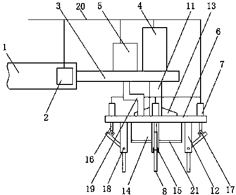
[0027] as attached image 3 As shown, a clamping structure of an industrial robot includes a positioning plate 1, a motor 2, a load plate 3, a cylinder one 4, a vacuum pump 5, a fixed plate 6, a cylinder two 7 and a clamping rod 8, and is characterized in that: The positioning plate 1 is provided with a limiting groove 9, the motor 2 is arranged on the positioning plate 1, a rotating shaft 10 is arranged on the motor 2, and the rotating shaft 10 is arranged in the limiting groove 9, the described One end of the bearing plate 3 is connected with the rotating shaft 10, the cylinder one 4 is arranged on the bearing plate 3, and the piston rod one 11 is arranged on the cylinder one 4, the described vacuum pump 5 is arranged on the bearing plate 3, and Vacuum pump 5 is provided with suction pipe 19, and described fixed plate 6 is arranged on the piston rod one 11, is provided with fixed rod 12, reinforcing plate 13, suction hood 14 on fixed plate 6, and on fixed rod 12 is provided...


PUM


Abstract

The invention provides a clamping structure of an industrial robot. The clamping structure comprises a positioning plate, a motor, a bearing plate, an air cylinder I, a vacuumizing pump, a fixing plate, an air cylinder II and a clamping rod. The clamping structure is characterized in that a limiting groove is formed in the positioning plate, the motor is arranged on the positioning plate, one endof the bearing plate is connected with a rotating shaft, the air cylinder I is arranged on the bearing plate, the vacuumizing pump is arranged on the bearing plate, the fixing plate is arranged on a piston rod I, the air cylinder II is arranged on the fixing plate, moreover, a piston rod II is arranged on the air cylinder II, the middle part of the clamping rod is arranged in a connecting groove through a connecting shaft, and a connecting plate is arranged at one end of the clamping rod. According to the clamping structure of the industrial robot, the bearing plate is arranged to be of a structure capable of rotating along with the rotating shaft, and the position of the bearing plate on the positioning plate is rotated, and therefore, a workpiece can be clamped from different angles, andthe working efficiency is improved.

Description

technical field [0001] The invention relates to a clamping structure, in particular to a clamping structure suitable for industrial robots. Background technique [0002] With the continuous improvement of the level of industrial technology, more and more industrial robots replace manual machining. However, in the process of workpiece processing by industrial robots, the firmness of the workpiece on the clamping structure of the industrial robot directly affects the processing quality of the workpiece. Most of the existing industrial robot clamping structures can only clamp a small number of types of mechanical workpieces. , reducing the versatility of the clamping structure, and there is also the problem of poor processing quality due to the low firmness of the workpiece on the clamping structure. Contents of the invention [0003] The purpose of the present invention is to overcome the problems of poor versatility, small scope of application, and poor processing quality ...

Claims


Application Information

Patent Timeline
Patent Type & Authority Applications(China)
IPC IPC(8): B25J15/02
CPCB25J15/02
Inventor 卢国孝钱国锐
Owner WUHU DEJIA INTELLIGENT TECH CO LTD
Why Eureka
Try Eureka