Rotation mechanism

A technology of a rotating mechanism and a turntable, applied in auxiliary devices, auxiliary welding equipment, welding/cutting auxiliary equipment, etc., can solve the problems of inconvenient welding operation, high cost of clamping devices, and inability to meet industrial needs, etc., to expand the scope of application, Simple structure and cost reduction effect

Pending Publication Date: 2018-01-19
GUANGZHOU RUISONG INTELLIGENT TECH CO LTD
View PDF5 Cites 4 Cited by
  • Summary
  • Abstract
  • Description
  • Claims
  • Application Information

AI Technical Summary

Problems solved by technology

However, when the workpiece is welded, different positions of the workpiece need to be welded, but at present, the orientation of the workpiece cannot be adjusted, which brings a lot of inconvenience to the welding operation; moreover, the existing clamping device includes a first clamping arm, a second The clamping arm, the first clamping arm and the second clamping arm are both driven by the air cylinder, so that the first clamping arm and the second clamping arm are close to or far away from each other, which is convenient for clamping the workpiece or loosening the workpiece
However, because the existing clamping device includes two cylinders, it needs to be equipped with an air distribution device, resulting in high cost of the clamping device, which is far from meeting industrial needs

Method used


Image

  • Rotation mechanism
  • Rotation mechanism
  • Rotation mechanism

Examples


Embodiment Construction

[0021] Below, the present invention will be further described in conjunction with the accompanying drawings and specific implementation methods. It should be noted that, under the premise of not conflicting, the various embodiments described below or the technical features can be combined arbitrarily to form new embodiments. .

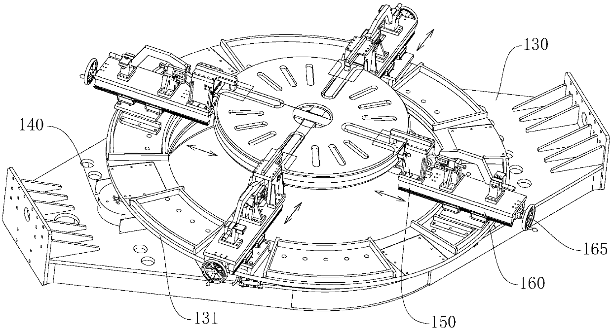
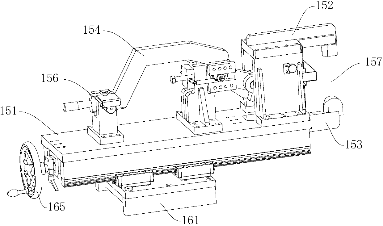
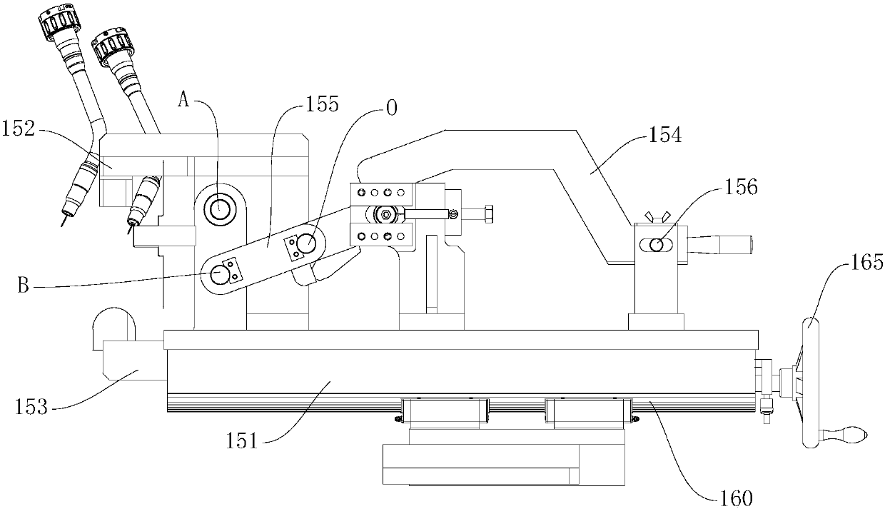
[0022] Such as Figure 1-4 The rotating mechanism shown includes a bearing base 130, a turntable 131 rotatably mounted on the bearing base 130, a driving device 140 for driving the turntable 131 to rotate around the central axis of the turntable 131 itself, and a circle around the central axis of the turntable 131. A plurality of clamping devices 150 arranged and commonly used for clamping workpieces, and several adjusting devices 160 corresponding to the several clamping devices 150 respectively; the clamping devices 150 are installed on the turntable through the corresponding adjusting devices 160 131, and each adjustment device 160 is used to guide...


PUM


Abstract

The invention discloses a rotation mechanism. The rotation mechanism comprises a bearing base, a rotary disc rotationally arranged on the bearing base, a drive device used for driving the rotary discto rotate around the center axis of the rotary disc, a plurality of clamping devices circumferentially arranged around the center axis of the rotary disc and jointly used for clamping workpieces, anda plurality of adjusting devices corresponding to the multiple clamping devices in a one-to-one manner. The clamping devices are arranged on the rotary disc through the corresponding adjusting devices, and the adjusting devices are used for guiding the corresponding clamping devices to move in the radial direction of the rotary disc. Each clamping device comprises a supporting base and further comprises a first clamping arm, a second clamping arm, a swinging rod, a connecting rod and an inserting piece, all of which are fixed to the supporting base. According to the rotation mechanism, the direction of the workpieces can be adjusted, meanwhile, the structure of the clamping devices is simple, air cylinders do not need to be adopted, and cost can be better reduced.

Description

technical field [0001] The invention relates to a rotating mechanism. Background technique [0002] During the workpiece welding process, the workpiece is jointly clamped by several clamping devices, and the several clamping devices are fixed on the bearing seat. However, when the workpiece is welded, different positions of the workpiece need to be welded, but at present, the orientation of the workpiece cannot be adjusted, which brings a lot of inconvenience to the welding operation; moreover, the existing clamping device includes a first clamping arm, a second The clamping arm, the first clamping arm and the second clamping arm are all driven by an air cylinder, so that the first clamping arm and the second clamping arm approach or move away from each other, which is convenient for clamping or loosening the workpiece. However, since the existing clamping device includes two cylinders, it needs to be equipped with an air distribution device, so that the cost of the clampin...

Claims


Application Information

Patent Timeline
Patent Type & Authority Applications(China)
IPC IPC(8): B23K37/047
Inventor 孙志强刘尓彬张国良吴潮辉郑杰才谭志军梁科伟
Owner GUANGZHOU RUISONG INTELLIGENT TECH CO LTD
Why Eureka
Try Eureka