Public broadcast main equipment cabinet

A technology for public broadcasting and main cabinets, which is applied to cabinets / cabinets / drawer parts, cabinets, cabinets for storing books, etc. performance, reduce the time spent, and improve the effect of the light environment

Inactive Publication Date: 2018-01-19
广州市鹭江远科技有限公司
1 Cites 3 Cited by

AI-Extracted Technical Summary

Problems solved by technology

[0004] In view of the deficiencies in the prior art, the purpose of the present invention is to provide a public broadcasting main cabinet to solve...

Method used

The problem solved by the present invention is that the internal light of the main cabinet is too dark, and it takes more time to search for items such as equipment and documents placed when searching. The present invention effectively improv...

Abstract

The invention discloses a public broadcast main equipment cabinet. The cabinet structurally includes drawers, a handle, cabinet doors, sliding cabinet plates, an induction lamp, idler wheels, a baffleand a cabinet body; the cabinet body is of a square stainless-steel structure and is formed by a plurality of steel plates, the inner cavity of the cabinet body is of a hollow structure, the outer side of the cabinet body is correspondingly provided with hinges, the left side of the surface of the cabinet body is provided with the handle, the drawers are arrayed in the inner cavity of the cabinetbody at equal intervals and can generate motion friction, the bottom of the cabinet body is provided with the idler wheels side by side, and the cabinet doors are movably connected to the two sides of the cabinet body in a hinge mode; the inner cavity of the cabinet body is provided with the sliding cabinet plates arrayed at equal intervals, and the baffle is arranged at the lower front side of the cabinet body; since the cabinet is provided with the induction lamp, by applying an electronic induction technique, in a dark environment or at night, a lamp bead is powered on and lightened, the inner light environment of the main equipment cabinet is effectively improved, the time consumption during searching can be greatly reduced, and the practicability of the cabinet body is improved effectively.

Application Domain

Technology Topic

Steel platesPublic broadcasting +3

Image

  • Public broadcast main equipment cabinet
  • Public broadcast main equipment cabinet
  • Public broadcast main equipment cabinet

Examples

  • Experimental program(1)

Example Embodiment

[0021] In order to make the technical means, creative features, objectives and effects of the present invention easy to understand, the present invention will be further explained below in conjunction with specific embodiments.
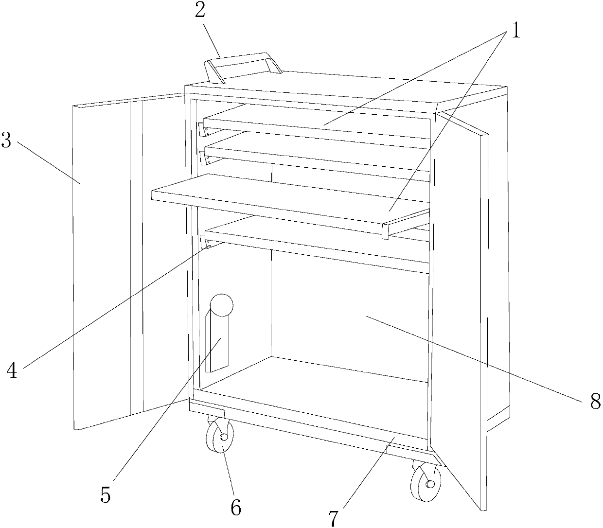
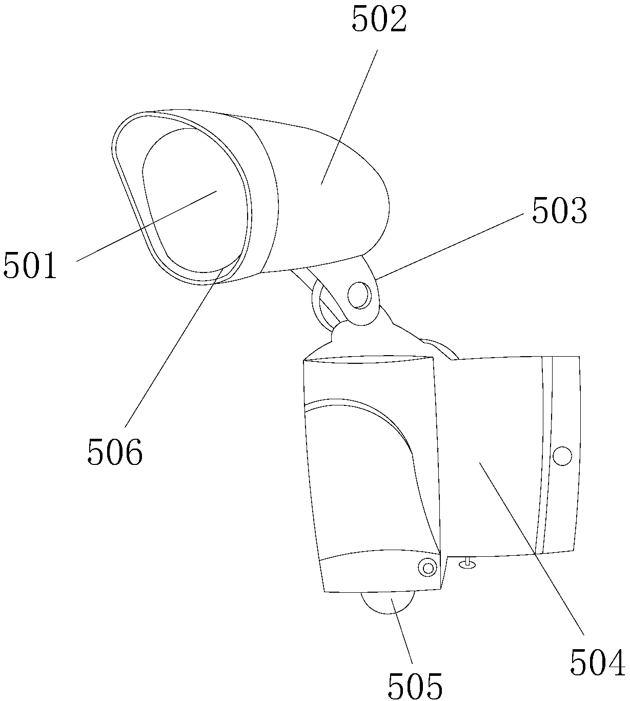
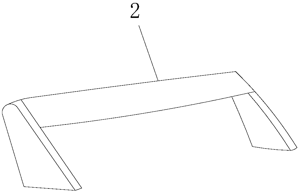
[0022] See Figure 1-Figure 4 , The present invention provides a technical solution: a public broadcasting host cabinet, the structure of which includes drawer 1, handle 2, cabinet door 3, sliding cabinet 4, induction lamp 5, roller 6, baffle 7, cabinet 8, so The outside of the cabinet 8 is a square stainless steel structure, which is composed of multiple steel plates. The inner cavity is a hollow structure. The outside of the cabinet 8 is correspondingly provided with hinges. The surface of the cabinet 8 is provided with a handle on the left side. 2. The drawers 1 are arranged equidistantly in the inner cavity of the cabinet 8 and move and rub. The bottom of the cabinet 8 is provided with side-by-side rollers 6, and the cabinet door 3 and the two sides of the cabinet 8 are movably connected by hinges. The inner cavity of the cabinet body 8 is provided with sliding cabinets 4 arranged equidistantly, the baffle 7 is arranged on the front and lower side of the cabinet body 8, and the inner cavity of the cabinet body 8 is provided with an induction lamp 5; the induction lamp 5 It is composed of lamp beads 501, a sensor 502, a movable part 503, an electric control box 504, a switch key 505, and a filter 506. The lamp beads 501 are electrically connected to the sensor 502, and the sensor 502 is connected to the filter. 506 is connected, the filter 506 is arranged on the front side of the lamp bead 501, the lamp bead 501 is connected to the electric control box 504, the lower end of the electric control box 504 is provided with a switch key 505, the rear wall is connected to the cabinet 8 The inner cavity is fixed with bolts. The roller 6 is located below the vertical corner of the cabinet door 3, the outside of the drawer 1 and the baffle 7 are on the same horizontal line, the sliding cabinet 4 is fixed, and the drawer 1 is placed inside and movable For connection, the cabinet door 3 is arranged at the outer front side of the drawer 1, and the handle 2 is located above the drawer 1 and has no direct connection relationship.
[0023] The sensor 502 mentioned in this patent is composed of a light sensor module, a heat sensor module, a delay switch module, and a signal processing module. The heat sensor module is responsible for detecting human thermal infrared rays, and the delay switch module is responsible for processing the light-on time range. The light sensor module Responsible for detecting the intensity of light.
[0024] When in use, when you need to find items such as equipment, documents, etc., first open the cabinet doors 3 on both sides of the cabinet body 8. The switch key 505 is connected to the electric control box 504 and is in the normally open state. In the daytime or in strong light Under the environment, the electrical signal value detected by the light sensor module of the sensor 502 will control the entire light in the locked state. In the dark or at night, the light sensor module will turn on the sensor light 5 in the light effect value detected. In the standby state, the thermal infrared rays are focused on the surface of the sensing element through the filter 506, and the human body infrared thermal sensor module is also activated. When a human body is sensed within its range, an electrical signal will be generated, which prompts the delay switch module to turn on the light , The lamp bead 501 is energized and lights up, which effectively improves the light environment inside the main cabinet, greatly reduces the time spent in the search process, and effectively improves the practicability of the cabinet 8.
[0025] The problem solved by the present invention is that the light inside the main cabinet is too dark, and it takes more time to search for items such as placed equipment and documents. The present invention effectively improves the internal light environment of the main cabinet through the combination of the above components, and greatly reduces the search The time spent in the process effectively improves the practicability of the cabinet. The details are as follows:
[0026] The lamp bead 501 is electrically connected to the sensor 502, the sensor 502 is connected to the filter 506, the filter 506 is arranged on the front side of the lamp bead 501, and the lamp bead 501 is connected to the electric control box 504 A switch key 505 is provided at the lower end of the electric control box 504, and the rear wall and the inner cavity of the cabinet body 8 are fixed by bolts.
[0027] The above shows and describes the basic principles and main features of the present invention and the advantages of the present invention. For those skilled in the art, it is obvious that the present invention is not limited to the details of the above exemplary embodiments, and does not deviate from the spirit or basics of the present invention. In the case of features, the present invention can be implemented in other specific forms. Therefore, from any point of view, the embodiments should be regarded as exemplary and non-limiting. The scope of the present invention is defined by the appended claims rather than the foregoing description, and therefore it is intended to fall within the claims. All changes within the meaning and scope of equivalent elements of are included in the present invention. Any reference signs in the claims should not be regarded as limiting the claims involved.
[0028] In addition, it should be understood that although this specification is described in accordance with the implementation manners, not each implementation manner only includes an independent technical solution. This narration in the specification is only for clarity, and those skilled in the art should consider the specification as a whole The technical solutions in the embodiments can also be appropriately combined to form other implementations that can be understood by those skilled in the art.

PUM

no PUM

Description & Claims & Application Information

We can also present the details of the Description, Claims and Application information to help users get a comprehensive understanding of the technical details of the patent, such as background art, summary of invention, brief description of drawings, description of embodiments, and other original content. On the other hand, users can also determine the specific scope of protection of the technology through the list of claims; as well as understand the changes in the life cycle of the technology with the presentation of the patent timeline. Login to view more.

Similar technology patents

Bus shelter with luminescent stand column

InactiveCN109898458AImprove securityImprove the lighting environmentLighting elementsElectric lightingSteel platesHorizontal diameter
Owner:JIANGSU RONGDA CULTURAL & CREATIVE CO LTD

Tunnel lighting control system

Owner:OCEANS KING LIGHTING SCI&TECH CO LTD +1

Method of manufacturing a head assembly

InactiveUS20080094754A1Efficient assembly processReduce time spentFluid-dynamic spacing of headsRecord information storageGimbalAdhesive
Owner:TOSHIBA STORAGE DEVICE CORP

Classification and recommendation of technical efficacy words

  • Improve the lighting environment
  • Reduce time spent

Tunnel lighting control system

Owner:OCEANS KING LIGHTING SCI&TECH CO LTD +1

Bus shelter with luminescent stand column

InactiveCN109898458AImprove securityImprove the lighting environmentLighting elementsElectric lightingSteel platesHorizontal diameter
Owner:JIANGSU RONGDA CULTURAL & CREATIVE CO LTD

Method and device for managing list item of content addressable memory CAM

InactiveCN101620623AReduce time spentReduce cache requirementsData switching networksSpecial data processing applicationsContent-addressable storageTernary content addressable memory
Owner:NEW H3C TECH CO LTD
Why Eureka
Try Eureka