Light-emitting surface structure of optical lens

An optical lens and light-emitting surface technology, applied in the field of lighting lamps, can solve the problems of errors, changing the surface curvature of the optical lens, and high difficulty in manufacturing molds.

Inactive Publication Date: 2012-03-21
DONGGUAN LEDLINK OPTICS
View PDF4 Cites 4 Cited by
  • Summary
  • Abstract
  • Description
  • Claims
  • Application Information

AI Technical Summary

Problems solved by technology

However, at present, various optical lenses such as: thermoplastics such as PC and PMMA are made by injection molding, and all kinds of optical lenses have a light-emitting surface, and an optical structure is generally arranged on the light-emitting surface. The shape is like a honeycomb, and it is formed by a plurality of hexagonal particles connected to each other. One side of the mold is provided with a plurality of hexagonal ribs facing the optical structure. Moreover, when the thermoplastic is molded in the mold, the thermoplastic will shrink when it cools, which will affect the dimensional accuracy of the optical lens in severe cases, and even change the optical lens. The curvature of the surface affects the overall projected illuminance, luminous angle and uniformity of luminosity

Method used


Image

  • Light-emitting surface structure of optical lens
  • Light-emitting surface structure of optical lens
  • Light-emitting surface structure of optical lens

Examples


Embodiment Construction

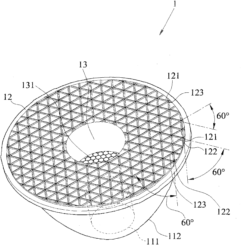
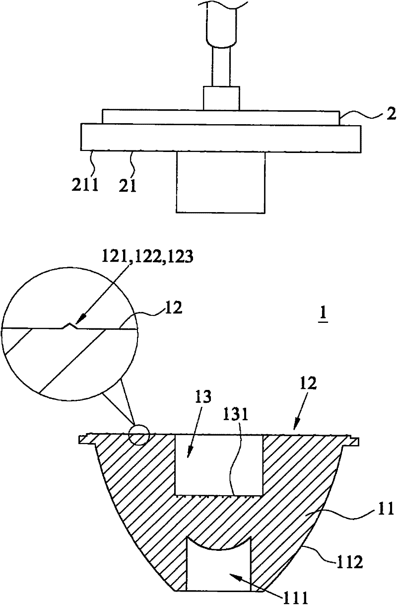
[0016] see figure 1 , 2 , 3, and 4 are schematic structural views of preferred embodiments of the present invention and partially enlarged schematic views, as well as cross-sectional views of various types of convex ribs. As shown in the figure, the structure of the light-emitting surface 12 of the optical lens 1 of the present invention is that the optical lens 1 is a lens body 11 of a conical structure. (not shown in the figure) constitutes a projecting curved surface 112, and a light-emitting surface 12 connected to the periphery of the projecting curved surface 112, the optical lens 1 is made of thermoplastic material through plastic injection molding, so the The mold 2 is provided with a molding surface 21 corresponding to the light emitting surface 12 , and a plurality of grooves 211 are provided on the molding surface 21 .

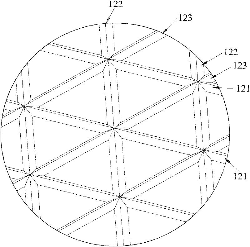
[0017] Wherein the first ribs 121, the second ribs 122 and the third ribs 123 on the light emitting surface 12, and the first ribs 121, the secon...


PUM


Abstract

The invention discloses a light-emitting surface structure of an optical lens. The optical lens is a lens body which is one of conical structural bodies. The lens body comprises a containing chamber, a projection curve surface and a light-emitting surface, wherein the projection curve surface consists of a plurality of curve surface points; the light-emitting surface is connected with the periphery of the projection curve surface; the light-emitting surface is provided with a plurality of first convex ribs, a plurality of second convex ribs and a plurality of third convex ribs in a staggered mode; and the first convex ribs, the second convex ribs and the third convex ribs are arrayed to form the configuration of a plurality of triangles. The structure provided by the invention is characterized in that the convex ribs on the light-emitting surface are utilized to form a structure similar to a prism or a convex lens, the light rays projected from the inner part of the optical lens can be diffused effectively and uniformly, and the manufacturing difficulty and the manufacturing cost of a mold can be lowered greatly.

Description

technical field [0001] The invention belongs to the field of lighting lamps, in particular to a light-emitting surface structure of an optical lens applied to LED lamps. Background technique [0002] According to general light emitting diodes (Light Emitting Diode, LED) because of its low power consumption, high efficiency, long life and other advantages, it is widely used in the light source of lighting (hereinafter referred to as LED light source). In recent years, LED light-emitting sources have been widely used in the field of lighting. Generally speaking, when comparing LED lighting equipment using LED light-emitting sources with traditional lighting fixtures under the same brightness conditions, the power consumption of LEDs is only that of ordinary incandescent lamps. 1 / 10 of that of energy-saving lamps, and 1 / 2 of energy-saving lamps, and the service life of LEDs has been greatly extended to more than 10,000 hours, which has the advantage of saving energy and electri...

Claims


Application Information

Patent Timeline
Patent Type & Authority Applications(China)
IPC IPC(8): F21V5/04F21Y101/02
Inventor 唐德龙
Owner DONGGUAN LEDLINK OPTICS
Why Eureka
Try Eureka