Table lamp capable of adjusting lighting direction and lighting range

An adjustable and azimuth technology, applied in lighting and heating equipment, components of lighting devices, lighting devices, etc., can solve the problems of inability to rotate in the horizontal direction, large lamp size, inconvenient carrying, etc., and achieve mass production , improve the lighting environment, significant creative effects

Inactive Publication Date: 2012-07-18
SHANGHAI QINSUN ELECTRIC CO LTD
View PDF6 Cites 4 Cited by
  • Summary
  • Abstract
  • Description
  • Claims
  • Application Information

AI Technical Summary

Problems solved by technology

[0002] Existing desk lamps usually include a base, a lamp cap, and a connecting pole for supporting the lamp cap. The connecting pole is fixed on the base. This type of desk lamp is very bulky and takes up a large space no matter it is used or stored, and it is very inconvenient to carry; There are some folding table lamps on the market. The connecting lamp poles use mutually nested rods or bendable snake-shaped rods to adjust the height of the lamp head up and down, but the horizontal direction cannot be rotated by itself. It is often necessary to move the entire desk lamp to adjust the angle, which is inconvenient to use
Chinese utility model 200720053214.0 discloses a table lamp with multi-directional angle adjustment, which includes a base, a light pole connected to the base, and a lamp head connected to the light pole, and the base and the light pole are hinged by a first rotating block , the light pole and the lamp head are hinged through the second rotating block, so that the angle can be adjusted between the light head and the light pole, and between the light pole and the base. Although the lamp head and the light pole of the device can be rotated, both It can only rotate in the up and down direction, but cannot rotate at any angle in the plane direction, especially it cannot realize the free adjustment of the lighting area and intensity, and cannot meet some special lighting needs

Method used


Image

  • Table lamp capable of adjusting lighting direction and lighting range
  • Table lamp capable of adjusting lighting direction and lighting range
  • Table lamp capable of adjusting lighting direction and lighting range

Examples


Embodiment

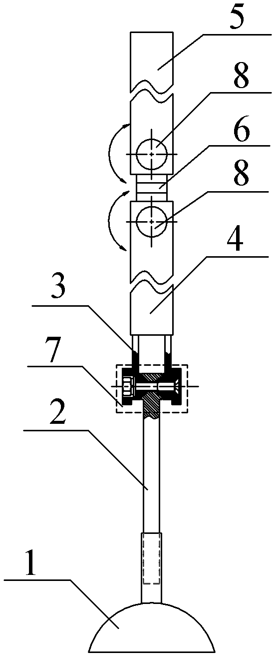
[0026] like figure 1 Shown: a table lamp with adjustable lighting orientation and range provided by the present invention, including base 1, support rod I 2, support rod II 3, lighting assembly A 4 spliced ​​at the end of support rod II3 in sequence along the straight line direction, lighting assembly B 5, the support rod I 2 is set on the base 1, the support rod II 3 and the support rod I 2 are connected through the rotating shaft-17, and the lighting assembly A 4 connected to the end of the support rod II 3 is connected to the support rod II The two are fixedly connected; the connection between lighting component A and lighting component B 5 is movably connected through the pivotal joint 6, and the space between lighting component A and the pivotal joint 6 and between the lighting component B 5 and the pivotal joint 6 are both Connected through the shaft-2 8.

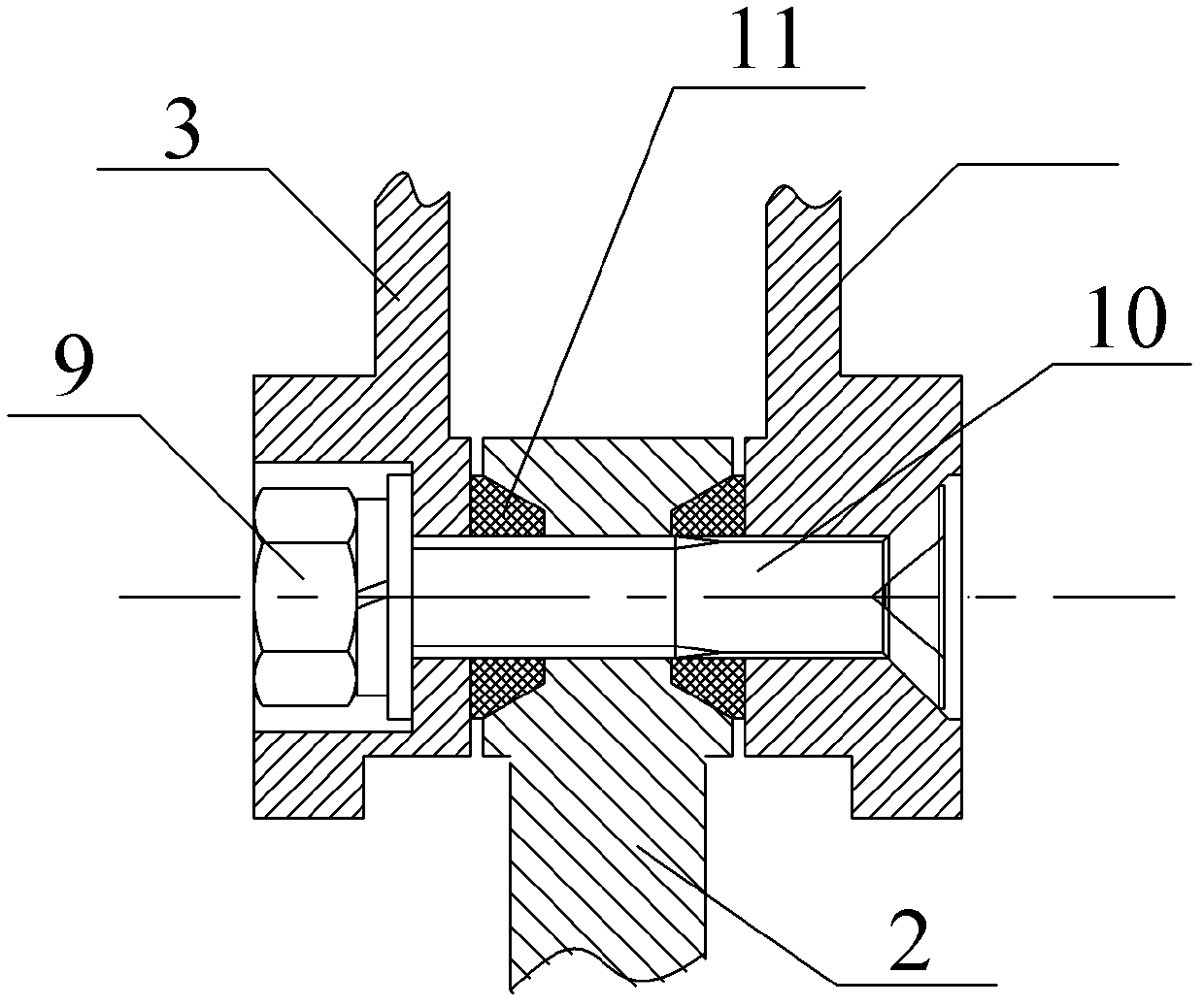
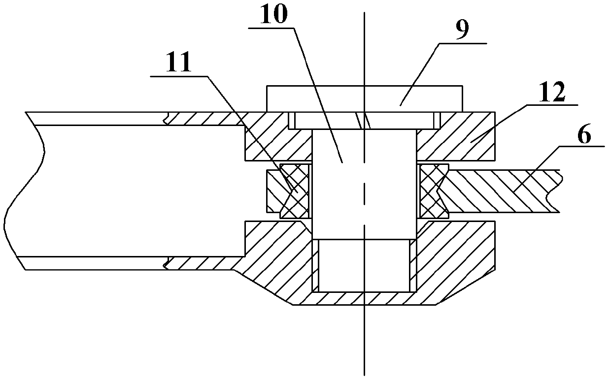
[0027] like figure 2 and image 3 As shown: the rotating shaft-17 and the rotating shaft-28 are formed by screw...


PUM


Abstract

The invention discloses a table lamp capable of adjusting the lighting direction and the lighting range. The table lamp comprises a base, a support rod I, a support rod II, and a plurality of lighting assemblies which are spliced at the tail end of the support rod II along the linear direction, wherein the support rod I is arranged on the base and is movably connected with the support rod II, a lighting assembly A connected with the tail end of the support rod II is fixedly connected with the support rod II, and the lighting assemblies are movably connected by pivoting pieces. The table lamp provided by the invention realizes the vertical and horizontal adjustment and further realizes the adjustment of the lighting area and strength, and meet any lighting demand. In addition, the invention has the advantages of wide applicability, obvious progresses and effects, simple structure and convenience in processing, can realize batch production, and is practical.

Description

technical field [0001] The invention relates to a desk lamp, in particular to a desk lamp with a foldable and extendable structure. Background technique [0002] Existing desk lamps usually include a base, a lamp cap, and a connecting pole for supporting the lamp cap. The connecting pole is fixed on the base. This type of desk lamp is very bulky and takes up a large space no matter it is used or stored, and it is very inconvenient to carry; There are some folding table lamps on the market. The connecting lamp poles use mutually nested rods or bendable snake-shaped rods to adjust the height of the lamp head up and down, but the horizontal direction cannot be rotated by itself. To adjust the angle on the lamp, it is often necessary to move the entire desk lamp for adjustment, which is inconvenient to use. Chinese utility model 200720053214.0 discloses a table lamp with multi-directional angle adjustment, which includes a base, a light pole connected to the base, and a lamp he...

Claims


Application Information

Patent Timeline
Patent Type & Authority Applications(China)
IPC IPC(8): F21S6/00F21V21/26F21V21/22
Inventor 王旭辉孙尚鹏于锡友李修章
Owner SHANGHAI QINSUN ELECTRIC CO LTD
Why Eureka
Try Eureka