Row exhaust fan

A technology for electric fans and fans, which is applied to non-variable-capacity pumps, components of pumping devices for elastic fluids, pump devices, etc., can solve problems such as not ideal, lack of exhaust electric fans, etc. handy effect

Inactive Publication Date: 2018-01-23
赵彦杰
View PDF0 Cites 0 Cited by
  • Summary
  • Abstract
  • Description
  • Claims
  • Application Information

AI Technical Summary

Problems solved by technology

[0002] At present, there is a lack of row-type electric fans on the market, which is not very ideal

Method used


Image

  • Row exhaust fan
  • Row exhaust fan

Examples


Embodiment 1

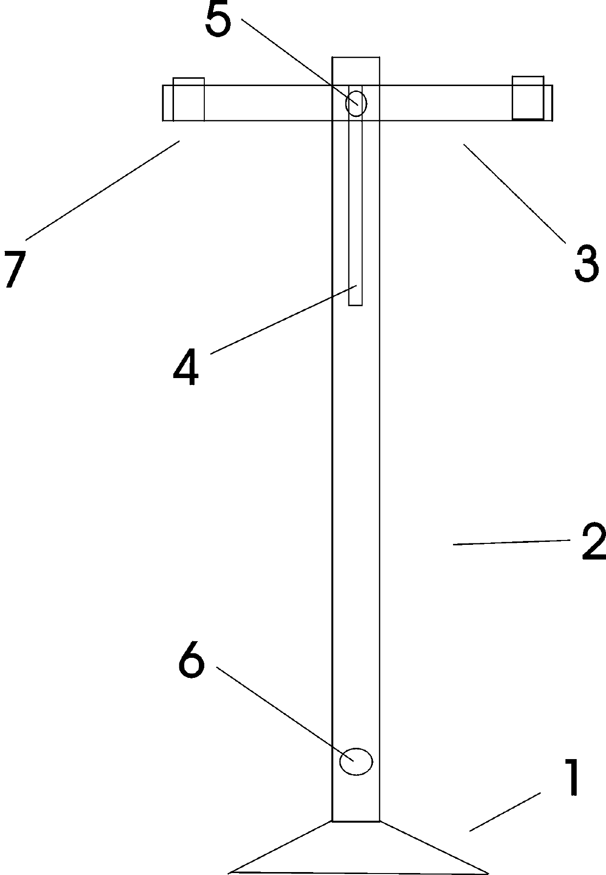
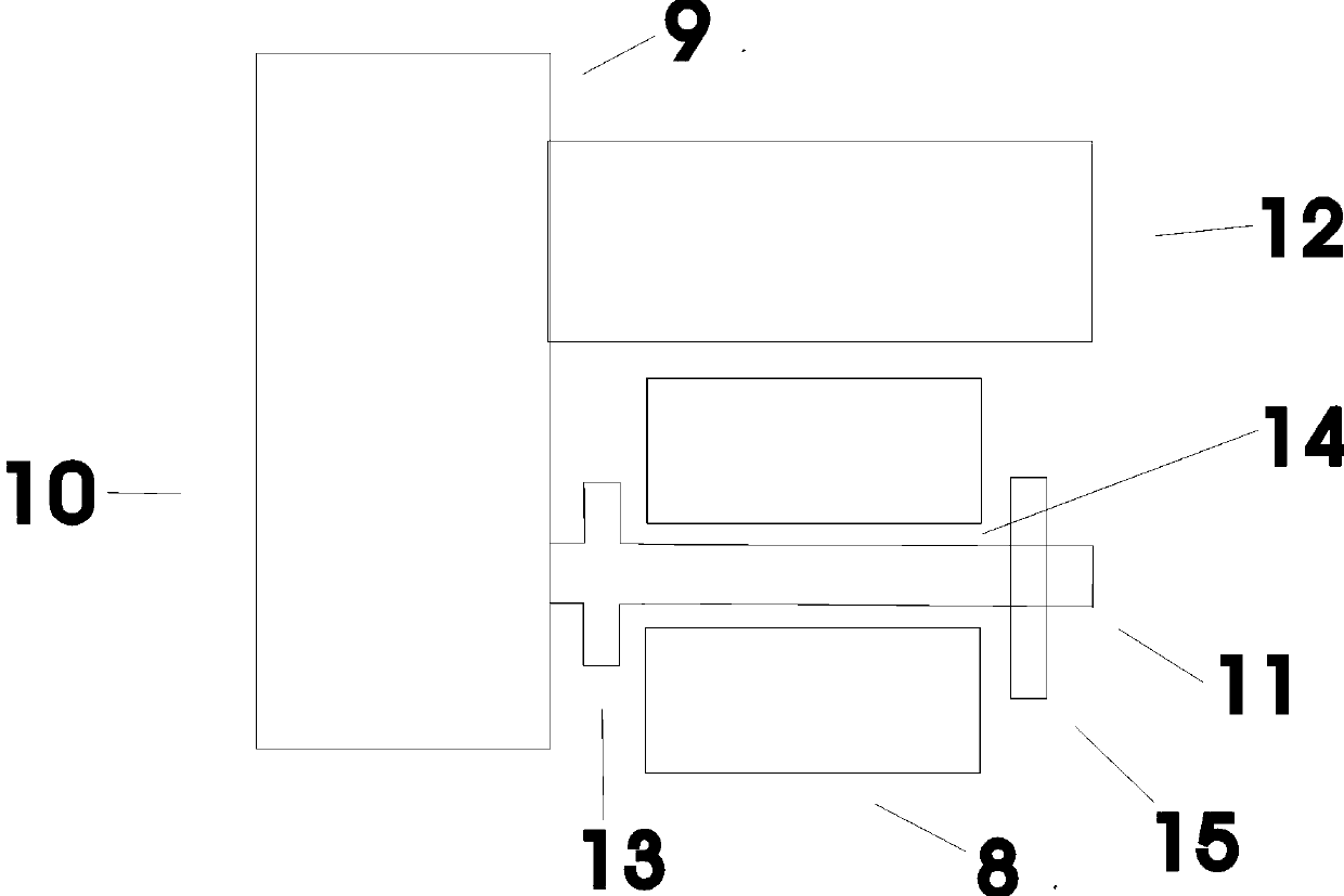
[0024] Embodiment one, row type electric fan, at first is to manufacture a setting frame. The setting stand has a base 1 . The base is placed on the ground in the shape of a disc. Or the base is in another shape. A setting bar 2 perpendicular to the ground is arranged on the base. Install a horizontal bar 3 perpendicular to the setting bar on the setting bar. The middle position of the horizontal rod is installed on the top of the setting rod. Or install in position under the top end of the setting rod. Or there is a slit 4 perpendicular to the ground on the setting rod. There is a screw hole 5 in the middle of the horizontal bar. Equipped with a set of screws, nuts and pads, the horizontal bar can be horizontally installed on the setting bar with screws, nuts, and pads. At the same time, the position of the horizontal bar on the setting bar can move up and down. Or mount a switchable light on top of the setting rod. The setting rod is hollow. An external power cord ...

Embodiment 2

[0029] Embodiment two, row type electric fan, at first be to manufacture a setting frame. The setting stand has a base 1 . The base is placed on the ground in the shape of a disc. Or the base is in another shape. A setting bar 2 perpendicular to the ground is arranged on the base. Install a horizontal bar 3 perpendicular to the setting bar on the setting bar. The middle position of the horizontal rod is installed on the top of the setting rod. Or install in position under the top end of the setting rod. Or there is a slit 4 perpendicular to the ground on the setting rod. There is a screw hole 5 in the middle of the horizontal bar. Equipped with a set of screws, nuts and pads, the horizontal bar can be horizontally installed on the setting bar with screws, nuts, and pads. At the same time, the position of the horizontal bar on the setting bar can move up and down. Or mount a switchable light on top of the setting rod. The setting rod is hollow. An external power cord ...

Embodiment 3

[0031] Embodiment 3. On the basis of Embodiment 2, the desk-top electric fan has the technology of swinging the head and shifting gears like the desk-top electric fans on the market now. Or there is desk lamp technology. All are existing technologies. Desktop fans have a power cord plug.


PUM


Abstract

The invention discloses a row exhaust fan. Firstly, an arrangement frame is manufactured. A base 1 is arranged on the arrangement frame. The base is placed on the ground in a disc form. The base is provided with an arrangement rod 2 perpendicular to the ground. A gap 4, perpendicular to the ground, is formed in the arrangement rod. A screw hole 5 is formed in the middle position of a horizontal rod 3. A set of screw, nut and pad is prepared, so that the screw, the nut and the pad for the horizontal rod can be horizontally mounted on the arrangement rod. An electric fan and a fan are mounted onthe horizontal rod. Or, two, three or more clamps are horizontally mounted on the horizontal rod. One table electric fan or table fan is clamped on each clamp. Or table clamp type electric fans or table clamp type fans are clamped. An external power supply wire insertion hole 6 is mounted at the lower part of the arrangement rod. An electric wire, connected with the external power supply wire insertion hole, is arranged from the hollowed arrangement rod to the horizontal rod. A plug of an external power supply wire is inserted in the external power supply wire insertion hole at the lower partof the arrangement rod, so that the row fan can be used. The angle can be adjusted as needed.

Description

technical field [0001] The invention relates to a row type electric fan. Background technique [0002] At present, there is a lack of row-type electric fans on the market, which is not very ideal. Contents of the invention [0003] In order to make it convenient for the public to take cool in an environment where the air conditioner cannot be used, the invention provides a row-type electric fan. The row-type electric fan is convenient for the public to cool off in an environment where air conditioners cannot be used. [0004] The technical scheme provided by the invention is: the row type electric fan, at first is to manufacture a setting frame. The setup stand has a base. The base is placed on the ground in the shape of a disc. Or the base is in another shape. There is a setting rod on the base that is perpendicular to the ground. Install a horizontal rod on the setting rod perpendicular to the setting rod. The middle position of the horizontal rod is installed on ...

Claims


Application Information

Patent Timeline
Patent Type & Authority Applications(China)
IPC IPC(8): F04D29/00F04D29/60F04D25/16
Inventor 赵彦杰
Owner 赵彦杰
Why Eureka
Try Eureka