Follower cooling structure for bilateral mechanical arm

A cooling structure and mechanical arm technology, applied in heating/cooling equipment, manufacturing tools, forging/pressing/hammer devices, etc., can solve the problems of untimely cooling, poor effect, and reduced mold life, etc., to achieve convenient cooling and structure Ingenious design and stable cooling effect

Active Publication Date: 2019-08-09
安徽康尼精密机械有限公司
View PDF10 Cites 0 Cited by
  • Summary
  • Abstract
  • Description
  • Claims
  • Application Information

AI Technical Summary

Problems solved by technology

The disadvantage of this lubrication method is that there will be a large amount of graphite vapor, which will cause environmental pollution in the workshop and is not worth promoting.
In the hot forging form with a large amount of water, the mold does not need to be heated, but it needs to be cooled in time to keep the mold at room temperature during the production process. The residual water on the surface of the mold is heated and vaporized into water vapor for lubrication during rapid forming. In time, the mold and forgings will have a phenomenon of bonding and a surge in ejection force, which greatly reduces the life of the mold, and som

Method used


Image

  • Follower cooling structure for bilateral mechanical arm
  • Follower cooling structure for bilateral mechanical arm
  • Follower cooling structure for bilateral mechanical arm

Examples


Embodiment 1

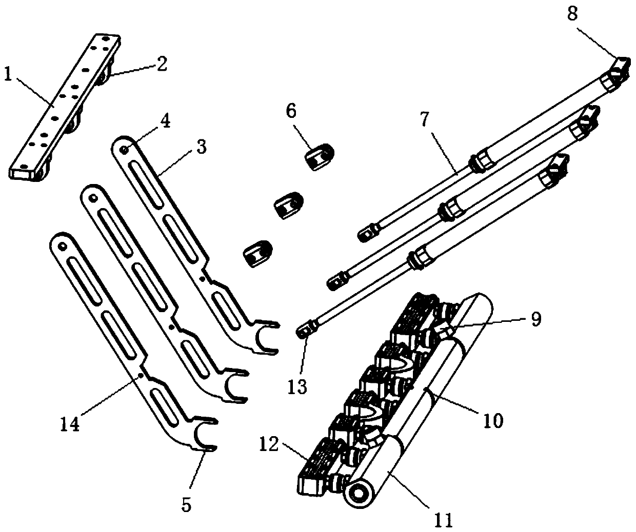
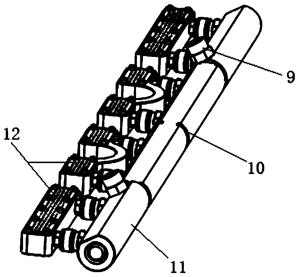
[0030] The follow-up cooling structure of the bilateral mechanical arm is applied between the upper mold frame 16 and the lower mold frame 17 of the hot forging machine, and is used for spraying cooling liquid toward the upper mold frame 16, combined with the attached figure 1 It can be seen that it includes a formwork connection base 1, a main connecting rod 3, a follower cylinder 7 and a nozzle module. The formwork connection base 1 is installed on the lower surface of the upper formwork, and the lower surface of the formwork connection base 1 is provided with several Each connecting joint 2 is connected to a main connecting rod 3, and the lower ends of all the main connecting rods 3 are connected to the nozzle module.

[0031] The upper end of the follower cylinder 7 is fixed to the upper mold frame, and the lower end is connected with the main connecting rod 3 near the lower end. The follower cylinder 7 stretches and pulls the main connecting rod 3 to rotate around the conn...

Embodiment 2

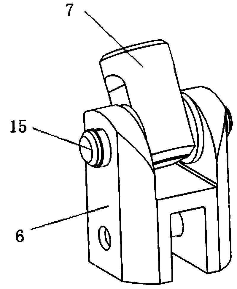
[0033] The relative positional relationship between the follower cylinder 7 and the main connecting rod 3 is further designed. The follower cylinder 7 and the main link 3 are located on both sides of the central axis of the upper mold base, forming a triangular structure with the upper mold base. When the upper mold base and the upper mold base When the lower mold base is separated, the nozzle module sprays coolant upwards. When the upper mold base and the lower mold base are closed, the follower cylinder 7 shrinks, pulling the main connecting rod 3 to move upward, and the main connecting rod 3 moves upward with the nozzle module. , the nozzle module always sprays coolant towards the heat concentrated area of ​​the upper mold base, and when the mold clamping is completed, the follower cylinder 7 shrinks to the shortest stroke.

Embodiment 3

[0035] The structure and connection relationship of the main connecting rod 3 and the follower cylinder 7 are further designed. The upper end of the main connecting rod 3 and the connecting joint 2 under the formwork connecting base 1 are movable connections, and the connecting joint 2 includes two parallel connecting plates. Both the top of the main connecting rod 3 and the connecting plate are provided with connecting holes 4, and the top of the main connecting rod 3 is inserted between the connecting plates so that the connecting holes 4 are aligned, and inserted into the connecting holes 4 by hinge bolts to realize the flexible connection. The main connecting rod 3 can rotate around the hinge bolt, and the two ends of the hinge bolt are connected with nuts to prevent it from falling off from the connecting hole 4 .

[0036] The top of the follow-up cylinder 7 is connected with the upper mold frame through a movable joint 8, and the follow-up cylinder 7 can rotate in the mov...


PUM


Abstract

The invention discloses a follower cooling structure for a bilateral mechanical arm. The follower cooling structure comprises a die frame connecting base, main connecting rods, follower cylinders anda nozzle module; the die frame connecting base is installed on the lower surface of an upper die frame; the lower surface of the die frame connecting base is provided with a plurality of connecting joints; each connecting joint is connected with one main connecting rod; the lower end of each main connecting rod is connected to the nozzle module; the upper end of each follower cylinder is fixed with the upper die frame, and the lower end of each follower cylinder is connected with the position, close to the lower end, of the corresponding main connecting rod; each follower cylinder stretches topull the corresponding main connecting rod to rotate around the corresponding connecting joint; and each main connecting rod drives the nozzle module to move. The follower cooling structure providedby the invention is applied between the upper die frame and a lower die frame of a hot forging die frame; and in the die closing and mold opening process, an angle of the follower cooling structure can be automatically adjusted, nozzles always spray cooling liquid towards a heat centralization region of the upper die frame, and the cooling effect is good.

Description

technical field [0001] The invention relates to a follow-up cooling structure of a bilateral mechanical arm and belongs to the technical field of hot forging machine cooling. Background technique [0002] The forging process carried out above the metal recrystallization temperature is called hot forging. Hot forging is also called hot die forging. During forging, the deformed metal flows violently, and the contact time between the forging and the die is longer. Therefore, mold materials are required to have high thermal stability, high temperature strength and hardness, impact toughness, thermal fatigue resistance and wear resistance, and are easy to process. [0003] In traditional hot forging, the mold needs to be heated to about 200°C, and the mold is lubricated by spraying graphite suspension on the surface of the mold. After evaporation, the residual graphite acts as a lubricating medium at high temperature. The disadvantage of this lubrication method is that there wi...

Claims


Application Information

Patent Timeline
IPC IPC(8): B21K29/00B21J1/06
CPCB21J1/06B21K29/00
Inventor 陈赟辉袁天宇
Owner 安徽康尼精密机械有限公司
Why Eureka
Try Eureka