Air conditioner unit control method and device

An air-conditioning unit and control method technology, applied in heating and ventilation control systems, refrigerators, heating methods, etc., can solve problems such as compressor damage and excessive refrigerant intake.

Inactive Publication Date: 2018-01-23
GREE ELECTRIC APPLIANCES INC
View PDF8 Cites 15 Cited by
  • Summary
  • Abstract
  • Description
  • Claims
  • Application Information

AI Technical Summary

Problems solved by technology

[0004] The embodiment of the present invention provides a control method and device for an air-conditioning unit, so as to at least solve the...

Method used


Image

  • Air conditioner unit control method and device
  • Air conditioner unit control method and device
  • Air conditioner unit control method and device

Examples


Embodiment Construction

[0022] In order to make those skilled in the art better understand the solutions of the present invention, the technical solutions in the embodiments of the present invention will be clearly and completely described below with reference to the accompanying drawings in the embodiments of the present invention. Obviously, the described embodiments are only Embodiments are part of the present invention, but not all embodiments. Based on the embodiments of the present invention, all other embodiments obtained by persons of ordinary skill in the art without creative efforts shall fall within the protection scope of the present invention.

[0023] It should be noted that the terms "first", "second" and the like in the description and claims of the present invention and the above drawings are used to distinguish similar objects, and are not necessarily used to describe a specific sequence or sequence. It is to be understood that the data so used may be interchanged under appropriate ...


PUM


Abstract

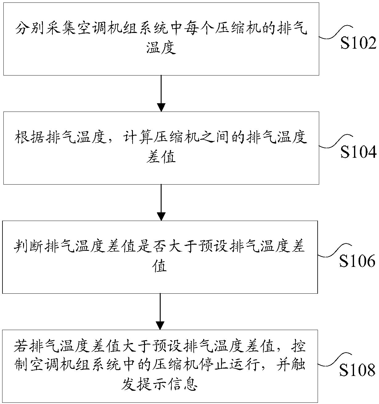
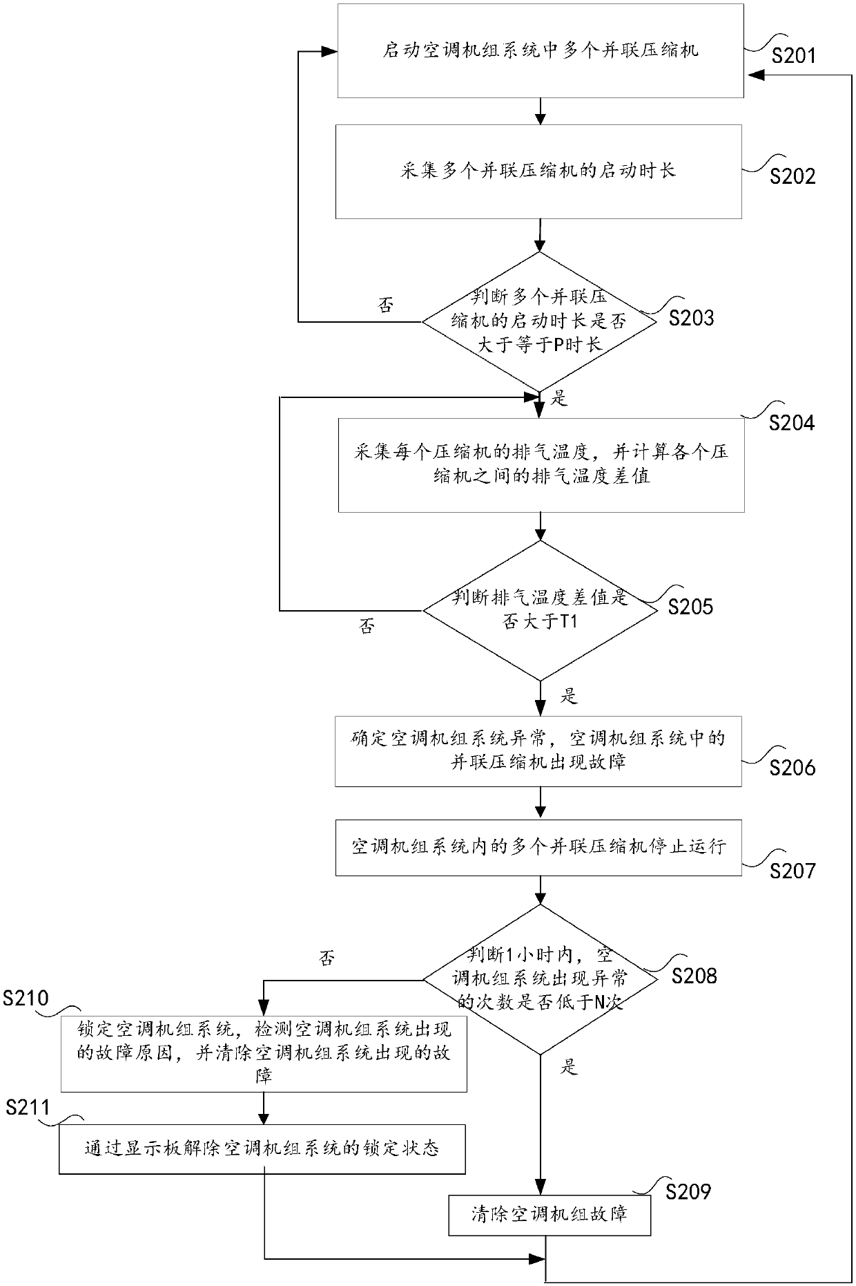
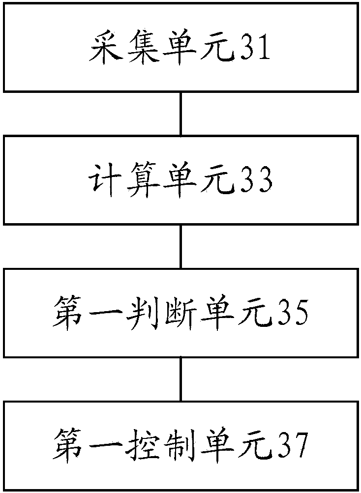
The invention discloses an air conditioner unit control method and device. The air conditioner unit control method comprises the steps that the exhaust temperature of each compressor in an air conditioner unit system is collected; according to the exhaust temperatures, the exhaust temperature difference value between the compressors is calculated; whether the exhaust temperature difference value is larger than a preset exhaust temperature difference value is judged; if the exhaust temperature difference value is larger than the preset exhaust temperature difference value, the compressors in the air conditioner unit system are controlled to stop operation, and prompt information is triggered, wherein the prompt information is used for reminding people that the air conditioner unit breaks down. The air conditioner unit control method and device solve the technical problem that in the relevant prior art, the parallel compressors in the air conditioner unit are damaged since the refrigerant suction volume is excessively large.

Description

technical field [0001] The present invention relates to the technical field of air conditioning control, and in particular, to a control method and device for an air conditioning unit. Background technique [0002] In the related art, if there are multiple parallel compressors in an air conditioning unit system, the pipeline structures of the compressors may be roughly the same, and the refrigerant flow rates and operating parameters of the compressors in the system are similar. If one or more compressors in multiple parallel compressors have too much refrigerant intake, it will lead to excessive liquid on one side of the system (such as the suction side), resulting in overloaded operation of the compressors, which will cause a long time. The overload operation of the compressor will cause the compressor motor to suffer from thermal shock, which will eventually cause damage to the compressor. [0003] Aiming at the above-mentioned technical problem that the parallel compres...

Claims


Application Information

Patent Timeline
IPC IPC(8): F24F11/64F24F11/38F25B49/02
Inventor 吴迪梅正茂李游孙亚丽
Owner GREE ELECTRIC APPLIANCES INC
Why Eureka
Try Eureka